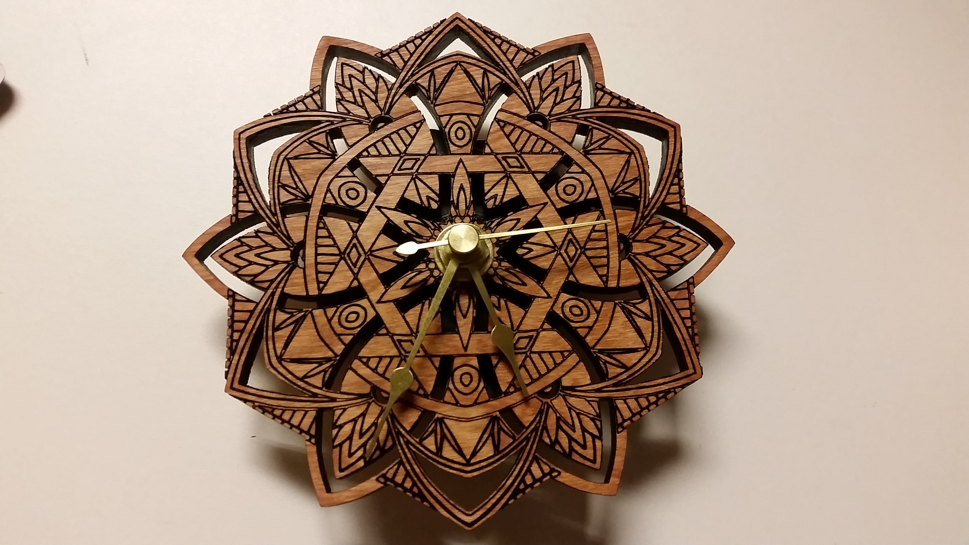
Here’s another relatively artistic project. I made this clock as a gift for someone:
Laser cut clock with a 12-point mandala face
The build was pretty straightforward. First, I searched online for mandala designs, and I started with one that I liked. The hardest part of this stage was finding designs that were 12-pointed; most mandalas have a 2^n number of points.
Next, I used Inkscape to vectorize the mandala and modified it to be appropriate for laser cutting. This included selecting parts to be engraved and cut as well as some tweaks to the design. I like making renderings to give me an idea of what the final project will look like, so I added some additional layers and a woodgrain bitmap to produce this preview.
This image gives a picture as to what the mandala would look like before laser cutting; I could use the same technique to visualize other designs cut and etched in cherry wood.
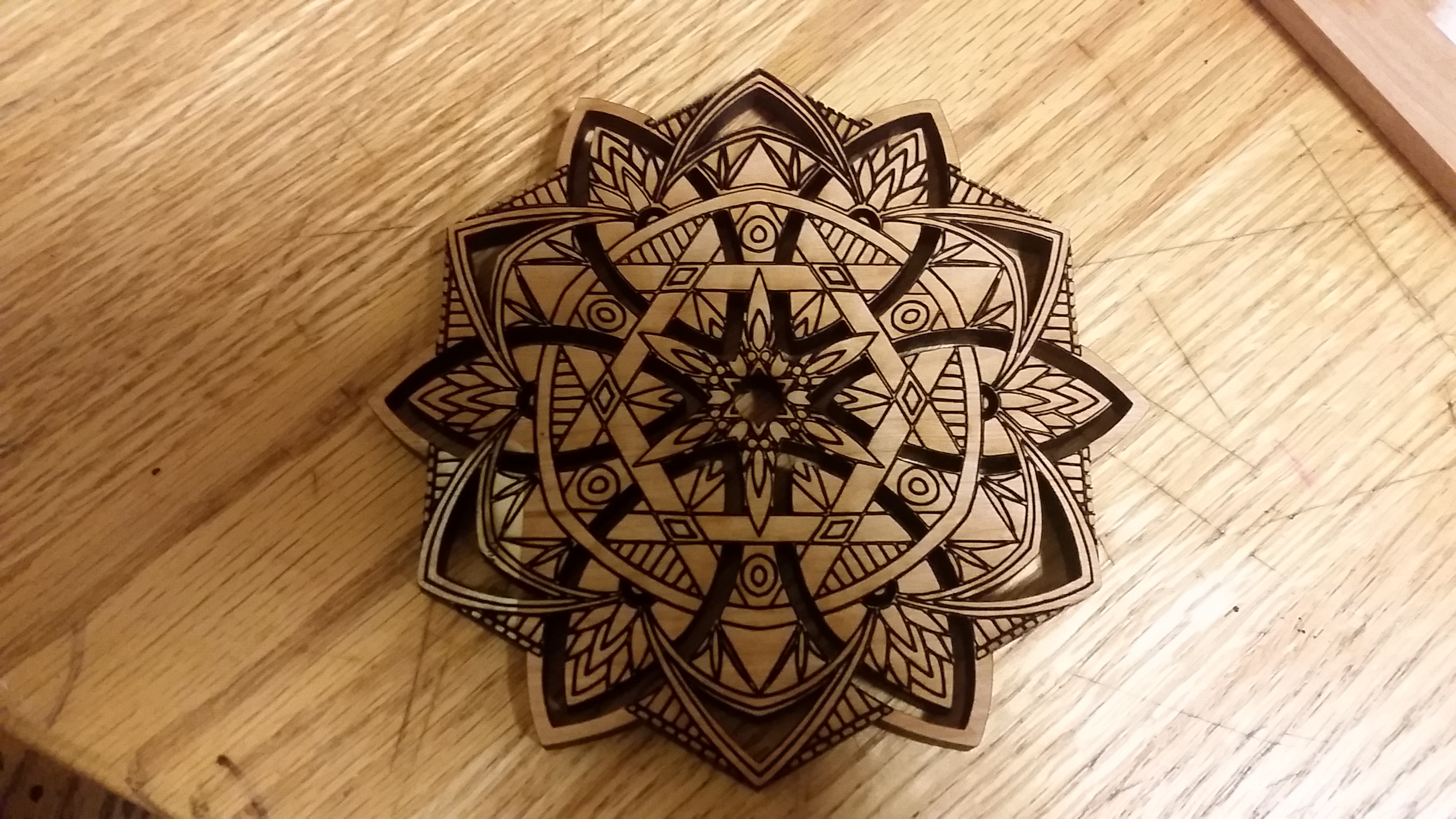
Satisfied with the design, I purchased some 1/4″ cherry wood and lasered it out.
Before cutting, I covered the piece in masking tape to protect the finish. It was a pain to remove the masking tape from all the little regions, but the result looks good. You can still see a piece of tape on the piece in this picture.
I think settings on laser cutters always take some tuning, so, for reference, I used these settings on a 30W laser cutter.
Cutting power: 100%
Cutting speed 32%
Cutting frequency: 2500Hz
Raster power: 25%
Raster speed: 100%
Raster resolution: 500dpi
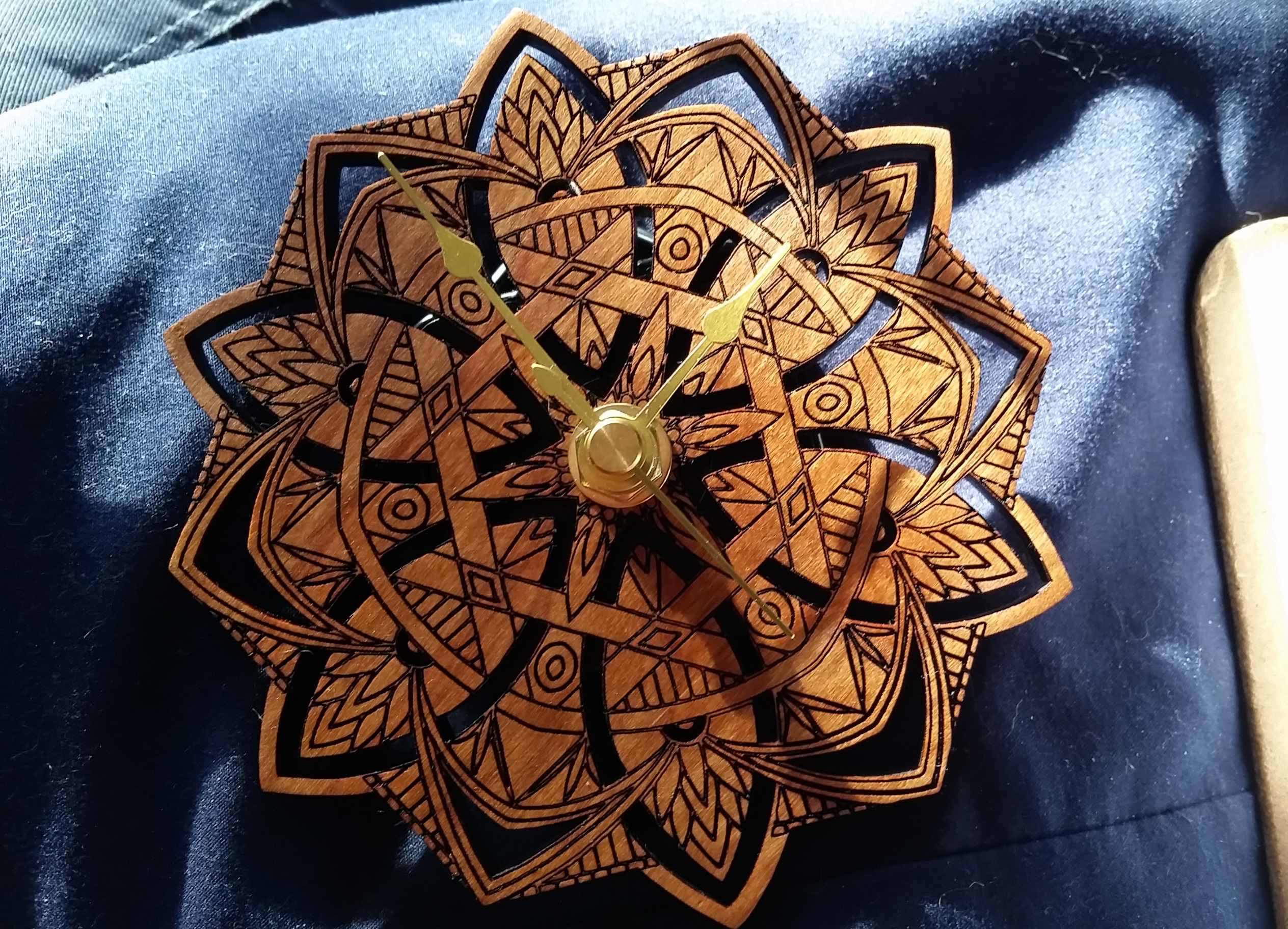
Next, I applied linseed oil to the result. I bought a small clock movement with brass parts, which I inserted into the hole in the face.
My favorite part is how the color changes depending on whether you’re looking at it along the grain or against the grain. One way, it looks golden, and the other way, it looks reddish in color.
Ok, this post is about catching up on an old project!
A semester ago, I took MIT’s Robotics: Science and Systems (6.141). I feel obligated to mention that, sadly, the instructor of this course Prof. Seth Teller has since passed away. On this topic, the MIT news office has a well-written article on Prof. Teller and his work. However, the focus of this post is going to be on the structure of the course and the final project.
My team used a few techniques to build this robot quickly and flexibly for our final project for 6.141.
It turns out there are several introduction to robotics classes at MIT. 6.141 is offered by Course 6, the Electrical Engineering and Computer Science department. However, there’s also Introduction to Robotics (2.12), offered by Course 2, the Mechanical Engineering department. Last semester, I took 2.12, and it’s safe to say that both 6.141 and 2.12 offer a hands-on introduction to robotics, but from different perspectives. 6.141 has a focus on algorithms related to robotics, such as those for navigation, motion planning, and machine vision. By contrast, 2.12 has a focus on analyzing mechanisms, like multijointed robotic arms or legs. The two classes had some overlap in their discussion of techniques for sensor fusion and filtering. 6.141 also offers an introduction to the Robot Operating System (ROS) and has a technical speaking and writing component. As someone who is interested in improving my public speaking skills, I thought the speaking component was fun. For students interested in robotics, I recommend taking both.
That said, Course 6 also offers an EECS survey class, 6.01. Though I hear 6.01 has changed since I took it, I found it was also a great class in terms of introducing students to problems and algorithms in robotics, perhaps as good as 6.141. For example, 6.01 included a series of labs in which students wrote code snippets for filtering, state estimation, and path finding, which ultimately allowed robotic vehicles to race through a maze. Like 6.141, the labs in 6.01 seem to build up to the notion of SLAM, starting with labs on simple navigation techniques and gradually becoming more advanced. However, unlike 2.12 and 6.141, 6.01 lacks a final project component.
The final project components was also how 2.12 and 6.141 differed. Ironically, although 6.141 was a computer science class, and 2.12 was a mechanical engineering class, I found I did mostly mechanical work for my 6.141 team and mostly software for my 2.12 team. I suppose this is because 6.141 attracted mostly computer science students, and 2.12 attracted mostly mechanical engineering students. For this reason, though, I’ll discuss the mechanical design of our 6.141 robot here.
The final challenge for 6.141 was to build, in a team of five, a robot to explore a room-sized arena, find colored blocks, and build a structure with them. We decided a neat way to further define the problem would be to build several towers of blocks, with each tower formed by only one color of block. We were also pressed for time, so I took a few steps to build this machine as fast as possible.
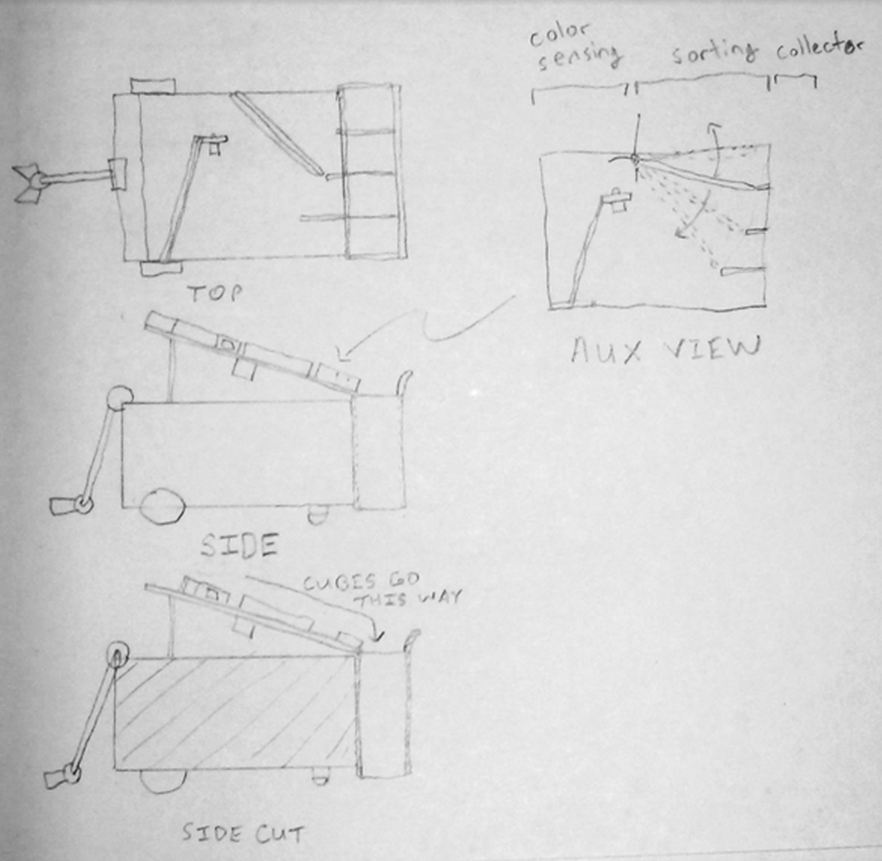
With this in mind, I decided the best way to design the hardware of the robot would be to break it up into physical modules. Each module could be designed independently, allowing people to design them in parallel, or at least reducing the cognitive load if one person worked on all modules. After consulting with the team, I settled on four: a chassis module, an arm/manipulator module, a block sorting module, and a storage module. The chassis would be the base of the robot and would include the frame, wheels, motors, battery, and laptop computer. The manipulator and arm would be mounted on the front of the chassis, able to pick up blocks from in front of the robot and drop them off on top of the robot. Atop the chassis would be mounted the block sorting module, which would sort and deliver blocks to the storage module, mounted to the back of the chassis. Finally, the storage module would feature a door or gate to release the blocks, stacked in tower formations.
This initial sketch of the robot included a fifth module: a color detection module attached to the front of the sorting module. However, we later decided to mount the color sensor on the claw itself, eliminating the need for color sensing while chanelling blocks.
Another convenience about the modular design of our robot was that it was really easy to take modules on and off. For example, to get at the electronics of our robot, mounted on the chassis, we could simply unscrew two screws and lift off the sorting mechanism.
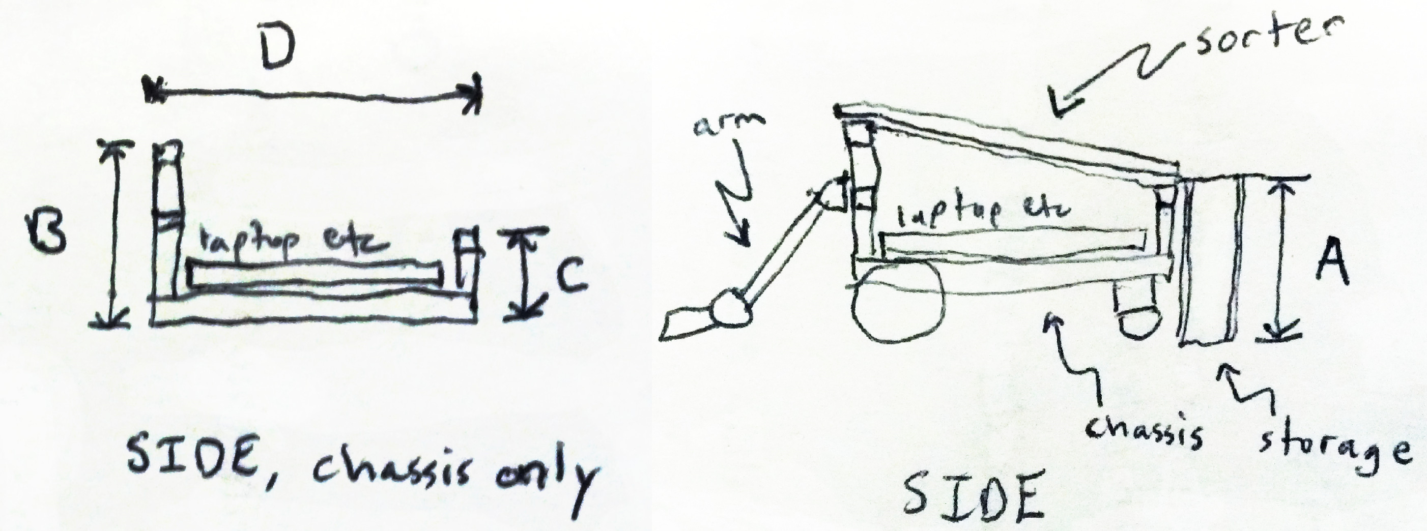
So that I could design each module separately, I first settled on the interfaces between the modules: each module would be able to attach to a separate horizontal bar of 80/20 aluminum extrusion attached to the chassis. I knew that I would want to adjust the exact heights and other dimensions of each module after I built the first prototype, so I deliberately designed these 80/20 bars to be adjustable in a few dimensions, such as height. Also, using the same technique as I detailed in my post about a window fan, I created a dimentions.txt file in which I recorded these dimensions. I used these as global parameters, which I referenced while designing each module, knowing their specifications for the connection points were the interfaces between each module.
At the start of creating CAD for the robot, I created a quick drawing to specify the meaning of dimensions A, B, C, and D in this drawing. I gave them names and specified them in dimensions.txt.
Also to cut down on construction time, I designed each module mostly out of 80/20 and laser cut acryllic. Using the laser cutter made it easy and fast to cut improved versions of parts. I also used Jesus Nuts for fast assembly.
The first two modules were straightforward. The chassis I designed was a slight adjustment from the squarebot chassis we had been using in labs earlier in the semester. Similarly, the arm and manipulator were re-used from earlier labs, but we added a color-detecting sensor to the manipulator to detect the color of the block being grasped.
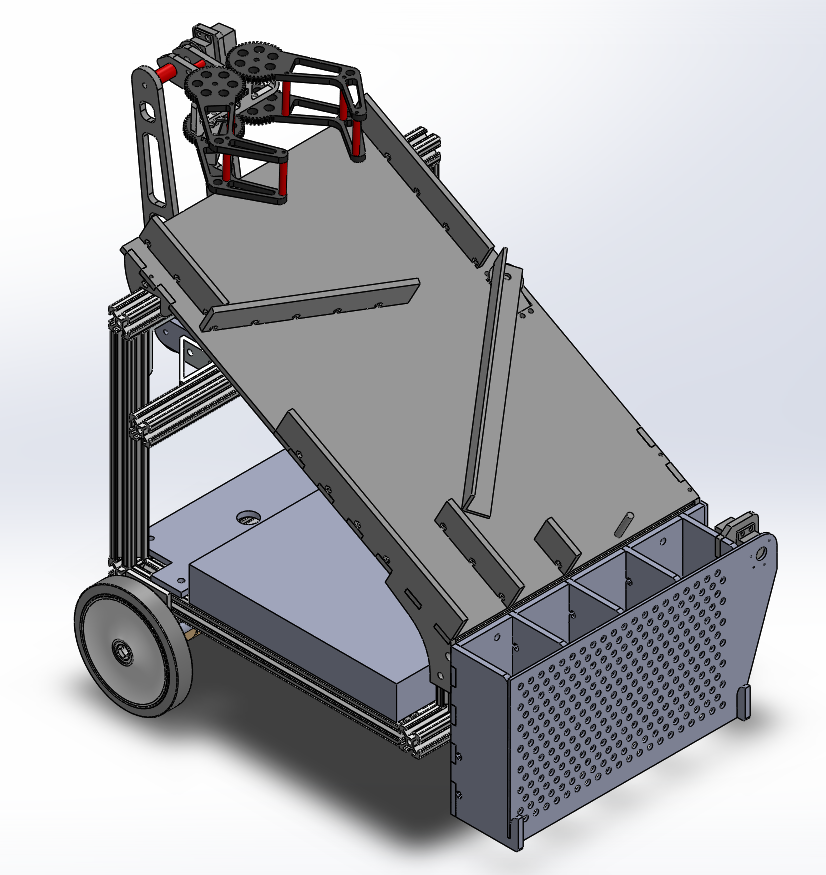
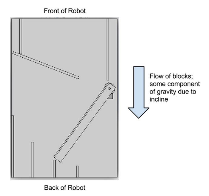
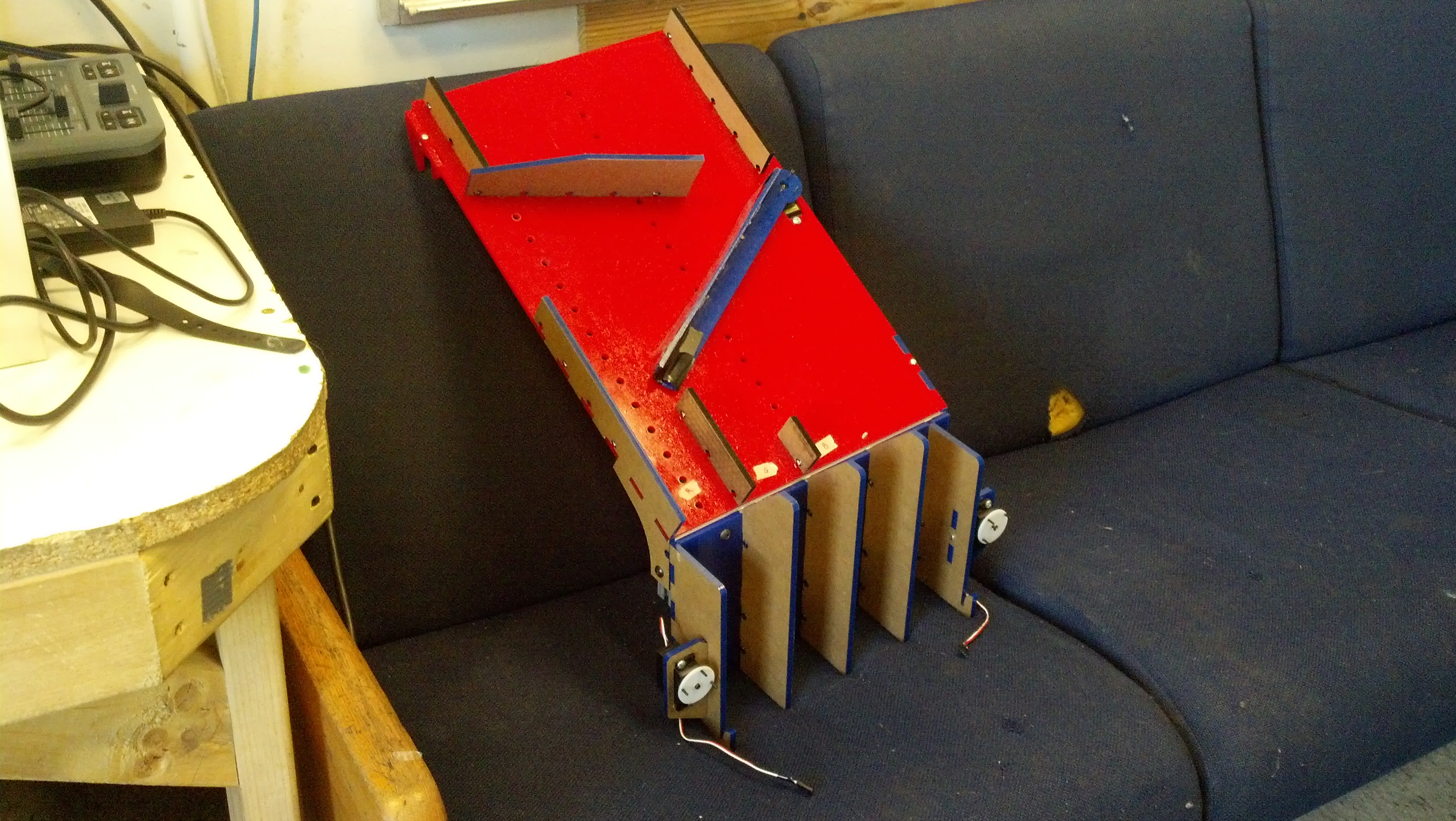
For the sorting module, we came up with a few options but settled on one that minimized the number of moving parts. The module consisted of a slanted panel with guides for blocks. First, the manipulator drops blocks off at the top. Then, one guide funnels all the blocks to one side of the robot. An actuated flipper then guides a block to one of four channels depending on the color of the block determined earlier from the color sensor.
This view, normal to the surface of the sorting mechanism, shows how blocks are first funneled to the flipper then channeled to a chute. Gravity pulls them down the mechanism.
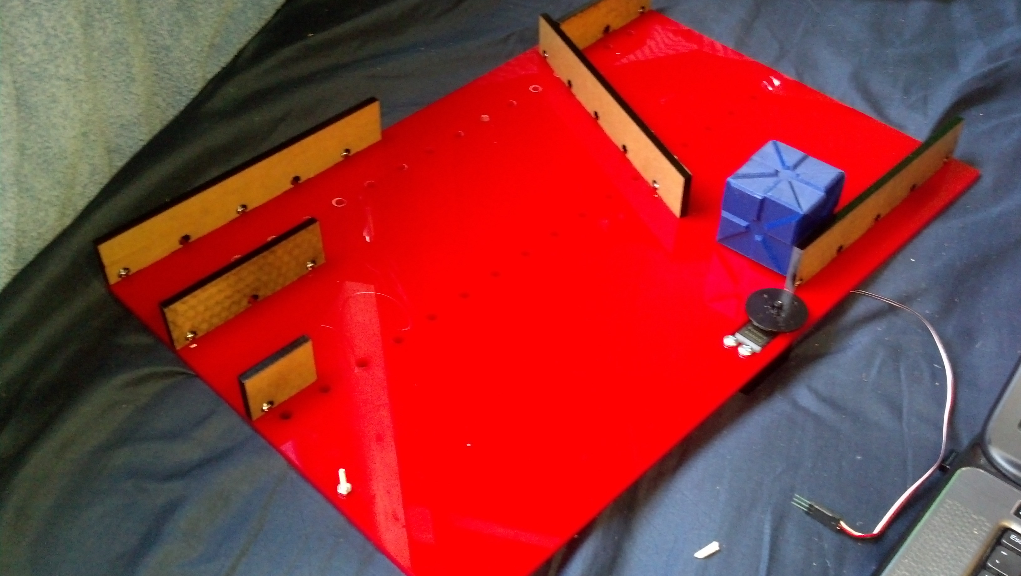
The first version of the sorter mechanism was fast to assemble and convenient for testing things like the minimum slope required for cubes to slip.
Finally, the collector module consists of four containers just big enough for cubes to stack one atop another. I created a few prototype single-column containers to determine the amount of extra room necessary to keep blocks from sticking to the wall. The containers were open on the top to allow blocks to slide in from the sorting module. I designed one side of the module to open, allowing the robot to drive away, leaving four towers of stacked blocks.
The final storage mechanism included four columns and a double door at the back. Here, the doors are removed to see inside the chutes. The final sorter module is also attached atop.
As mentioned earlier, these techniques allowed me to quickly make improvements to parts. For example, I increased the heights of certain walls that blocks were able to fall over, I increased the slope of the sorter to reduce the chance of blocks sticking, and I replaced the single door on the back of the storage mechanism with a double door mechanism because the weight of a single door was pushing the limit of what the servo could provide.
Unfortunately, I wasn’t able to collect much video footage before the disassembly of our robots, but the following two videos show our robot during testing and in action.
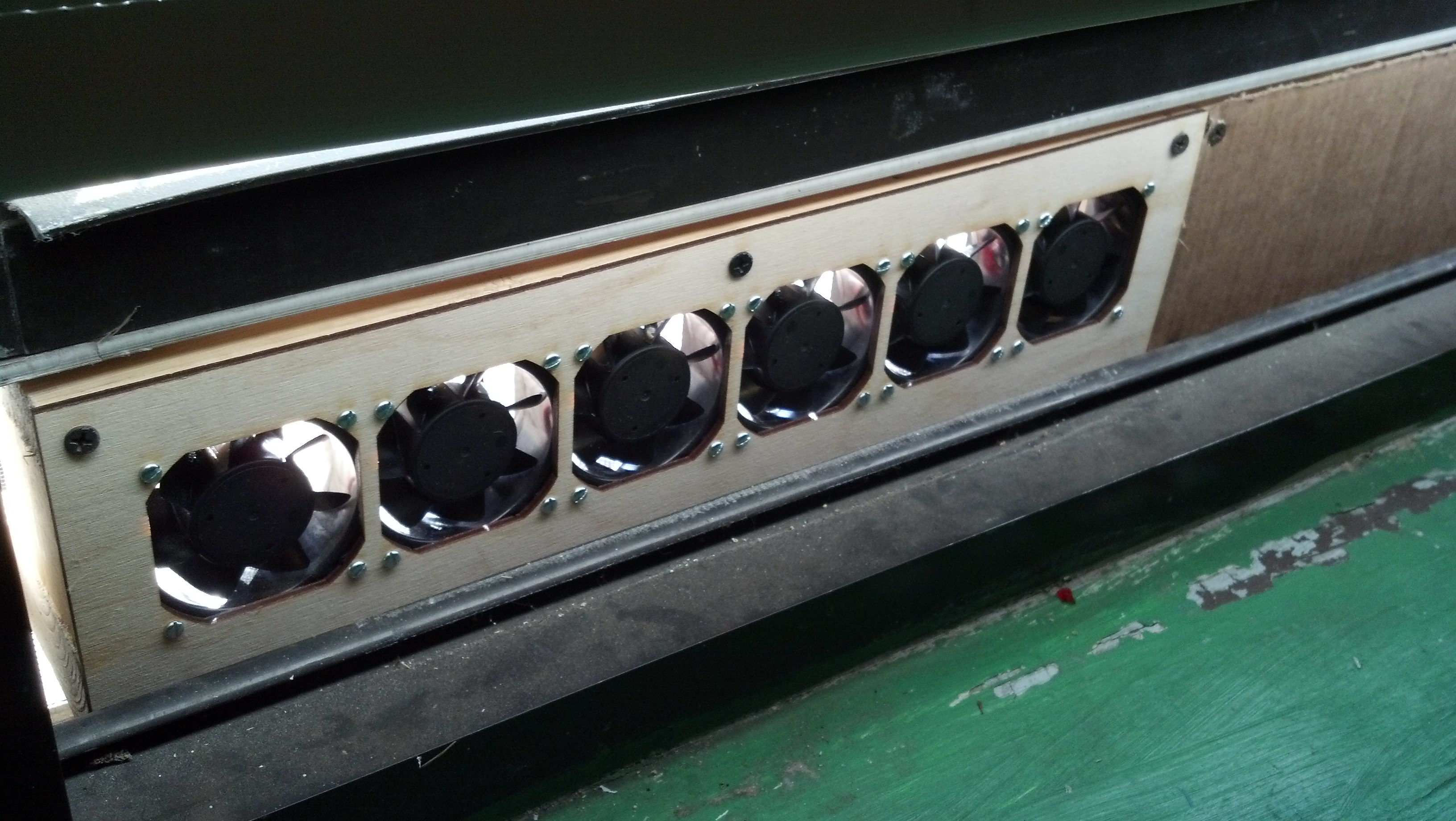
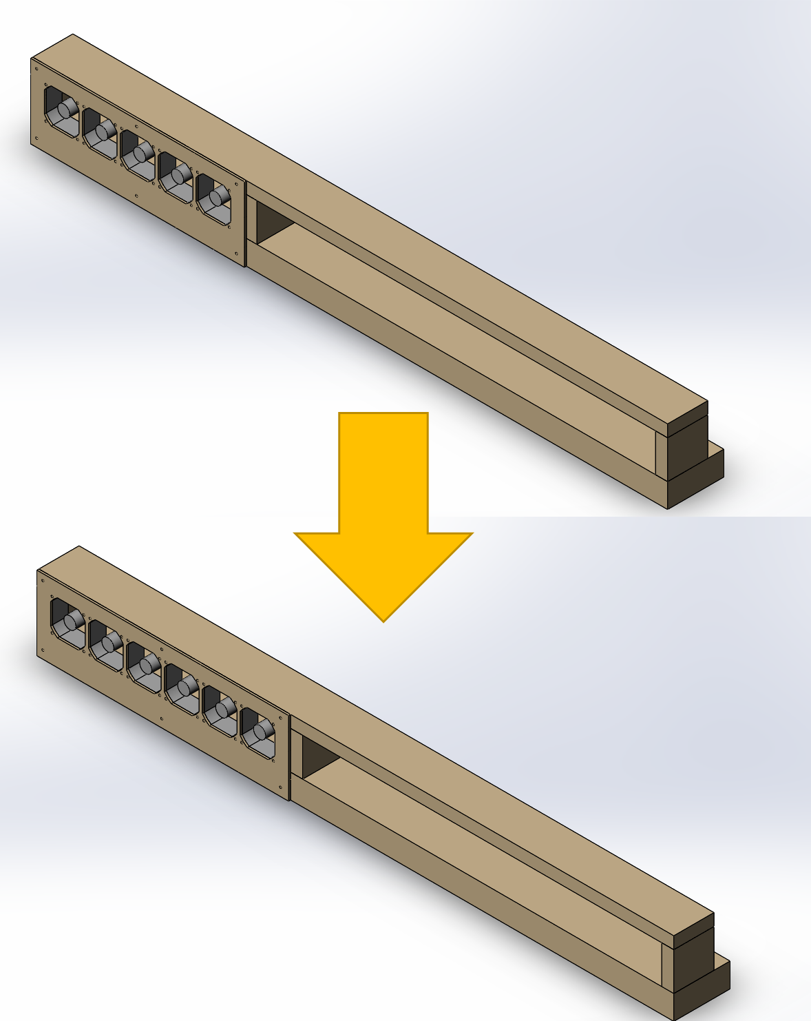
A few days ago I made a low-profile fan for my window out of computer fans. I wanted to mount the fans in a laser-cut frame, so I started by taking measurements and drafting the design in SolidWorks.
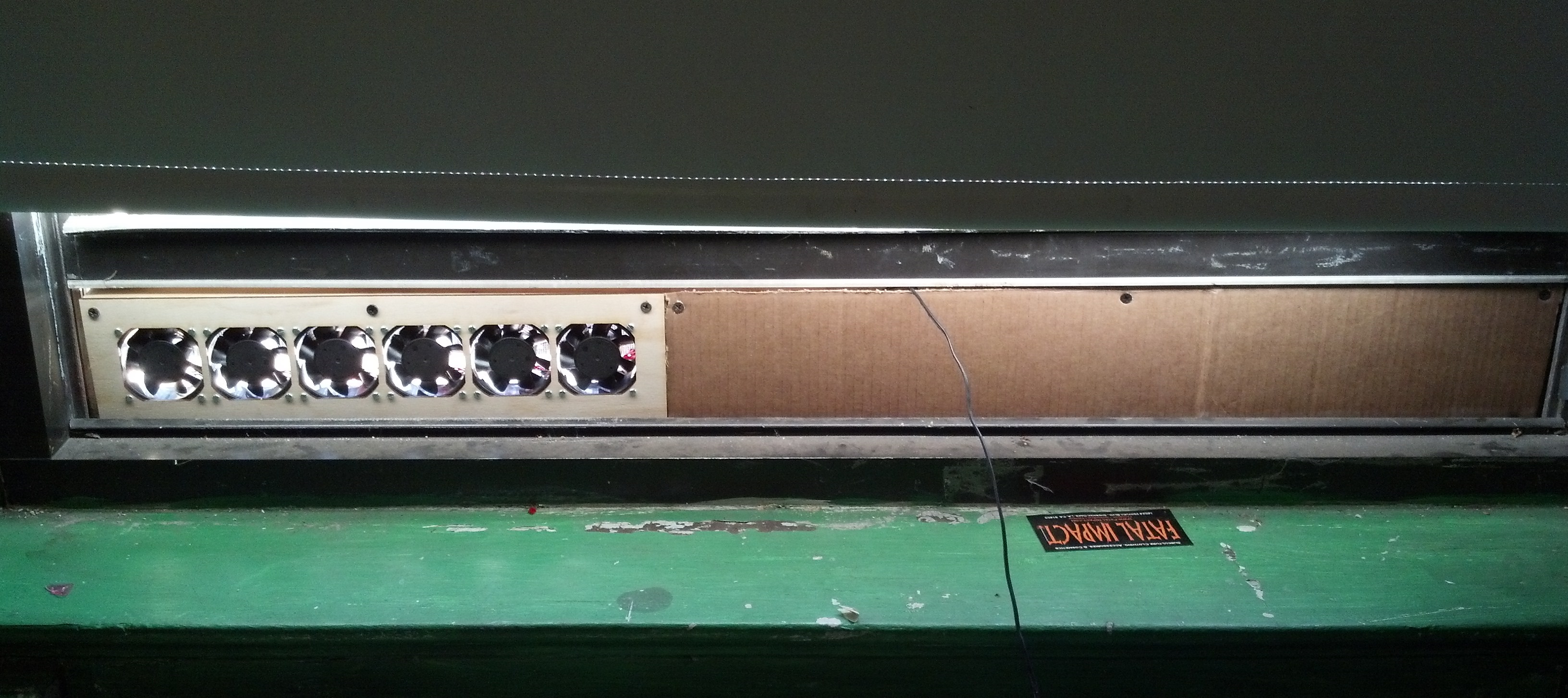
This row of fans takes up only a few vertical inches of window real estate.
Often, when I make a design in SolidWorks, I include a file for storing global variables for my project. I liken this to defining global variables or constants at the beginning of a software project. I use this technique frequently to great utility in SolidWorks, but I don’t see very many colleagues use it, so let me elaborate on it.
First, I make a text file called “dimensions.txt” or similar, and, in it, I list all the global variables I’d like to use in my project, like the example below. These include values that I’d like to be the same across parts files. I also include values that I think will have to be changed by the end of the project.
For example, for this project, I thought I might change what computer fan I used and how many I used, so I included mounting dimensions for the fan as well as the quantity of fans.
However, I knew the width of the window wouldn’t change, and was only used in one or two parts, so I didn’t include that constant in my list of project-wide constants.
There are some tricks to this text file–for SolidWorks to understand it, all variables must be enclosed in quotes ( ” ” ), comments must be preceded by a single quote ( ‘ ), and the file must end with a newline. Note that in the box above, the numbers on the left mark the lines but are not in the actual text file.
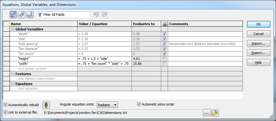
I save dimensions.txt in the root directory of my SolidWorks project. Then, whenever I make a new part, I first use the Equations dialogue in SolidWorks to import this file into the list of parameters for that part; the screenshot below shows the Equations dialogue after importing dimensions.txt. For a parametric modeling software, I think SW sure has this parameter dialogue tucked away, so I have it hotkeyed to Q, the same as the default in Autodesk Inventor, if I recall correctly.
In addition to the globals imported from dimensions.txt, I added a few values specific to this part, the front panel. These values in particular were derived from the globals in dimensions.txt, but they weren’t necessary to be known by every part in the assembly.
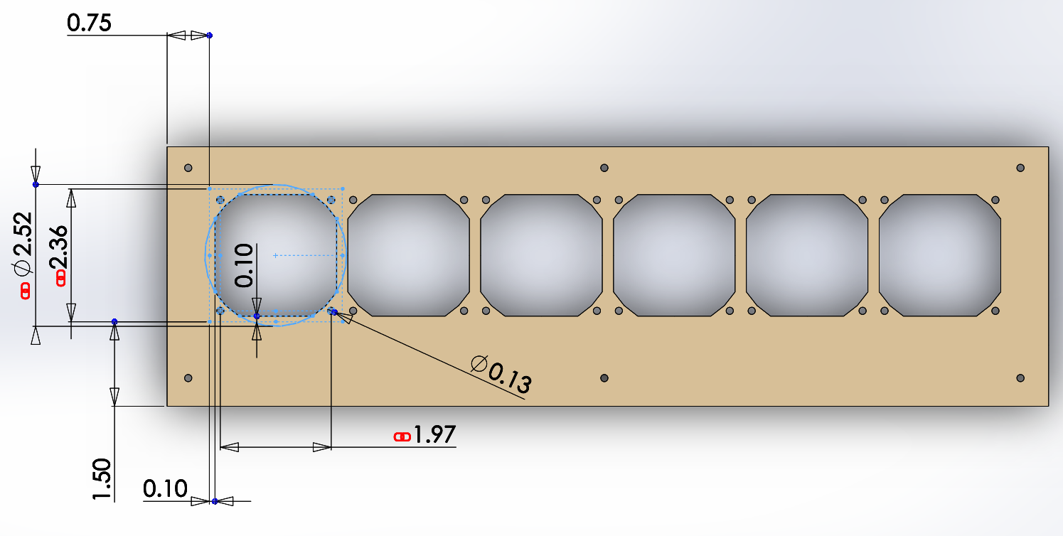
Then, whenever I dimension a sketch or feature in the part, I link those values to the global variables imported in dimensions.txt, as shown below.
I linked the values of the dimensions here to my global variables, as indicated by the red chainlink symbol.
This allows me to change parameters after I’ve finished the basic CAD. Whenever the part or assembly is rebuilt, SolidWorks automatically refreshes the values in dimensions.txt. Consequently, I can change one value with my text editor, rebuild the top-level assembly in SolidWorks (ctrl+b), and all files update their parameters from dimensions.txt.
This actually ended up being relevant for this project because I found an extra fan of the same size as my earlier ones, and I wanted to add it to the array. Due to this technique, this change required an order of magnitude fewer operations–my panel and assembly were updated immediately and automatically, as demonstrated below.
Changing from five fans to six required about two clicks instead of a dozen.
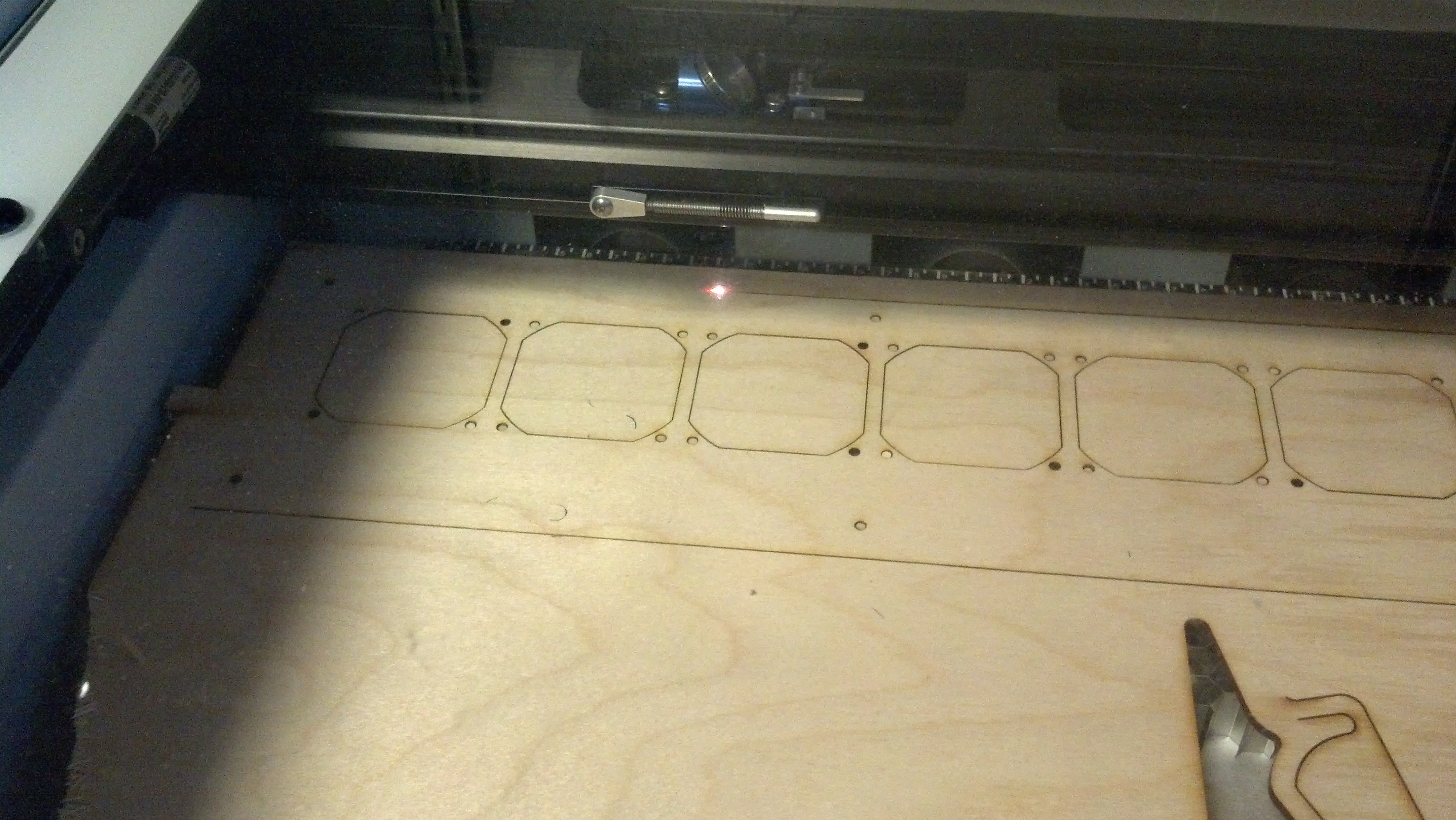
Anyway, after I made this design, I laser cut the front panel.
I’m a huge fan of how fast laser cutters are.
Then, I screwed it all together and ran it off of a 5V couple-Amp power supply.
I covered the rest of the fan box with a sheet of cardboard.
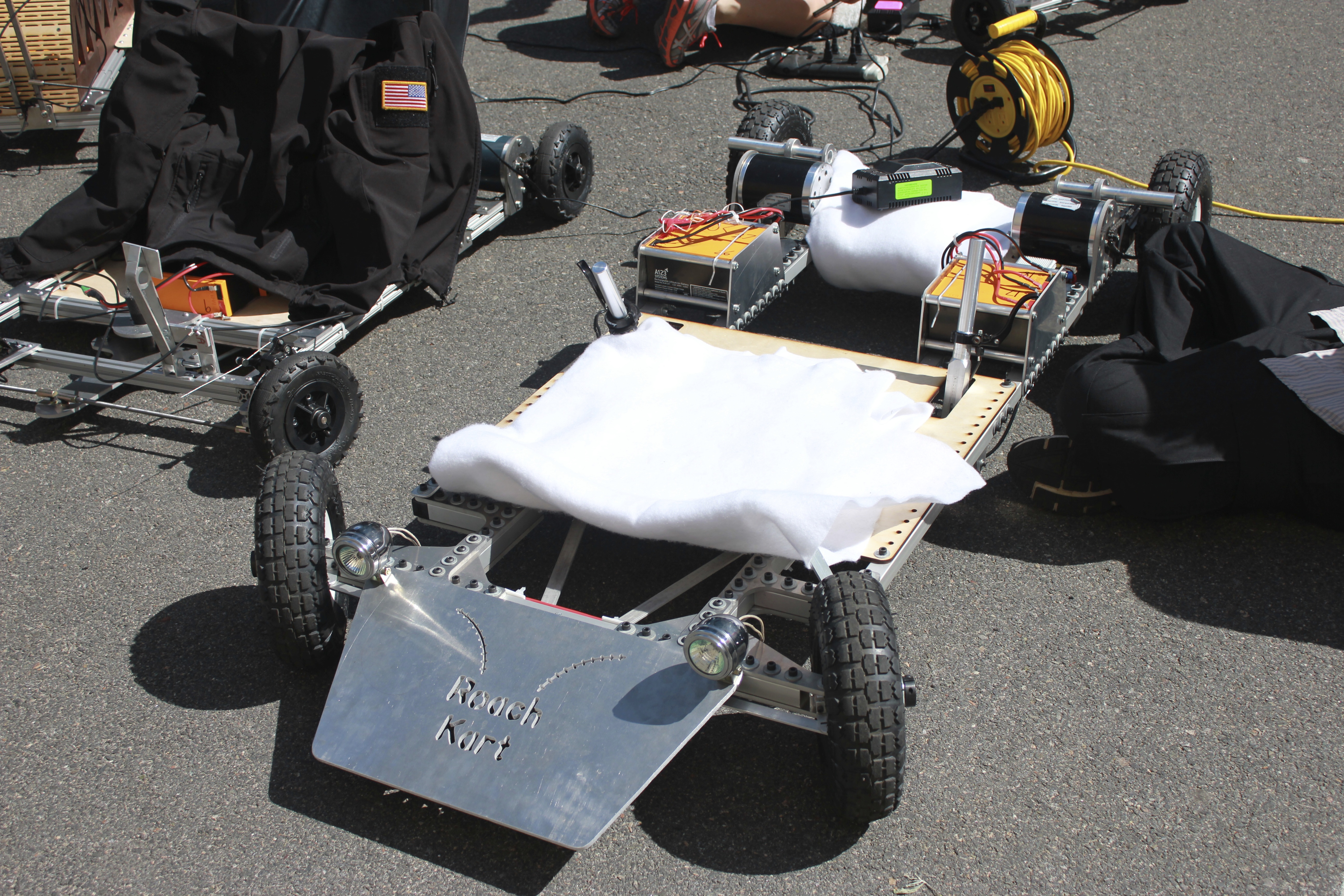
Last semester, I took a class called 2.007, Design and Manufacturing I, which is a project-based class offered by the mechanical engineering department at MIT (course catalog description). Normally, 2.007 students design and build robots for a competition at the end of the class, but this year 2.007 had two special sections: one for building underwater systems and one for building electric vehicles (EVs). I enrolled in the EV section, and over the course of the semester, my teammate Eric and I built an electric go kart, which we named RoachKart. At the end of the semester, we had a series of races. There’s a lot to say about the kart, but for now I’ll just outline our build process.
Karts charge prior to the race. Photo by Kirsten L
Our section was taught by EV extraordinaire Charles G, whose relevant blog is here, and who gave presentations on various aspects of vehicle design throughout the semester. At the beginning of the class, he gave constraints for our go karts–20 mph max speed, braking and steering systems, a $500 budget, and more. With this in mind, we set out designing a kart that would satisfy these criteria as well as being fun to drive.
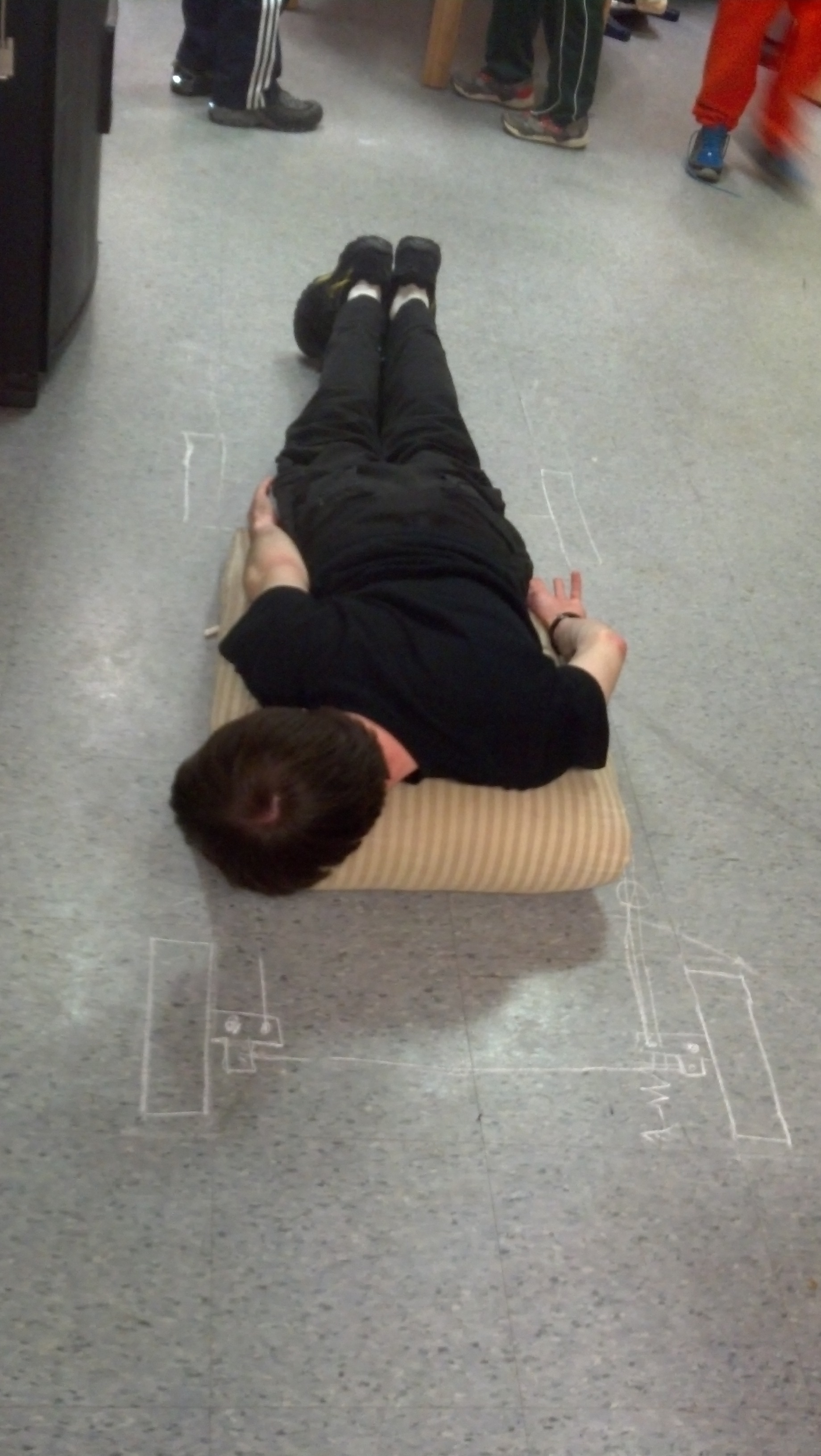
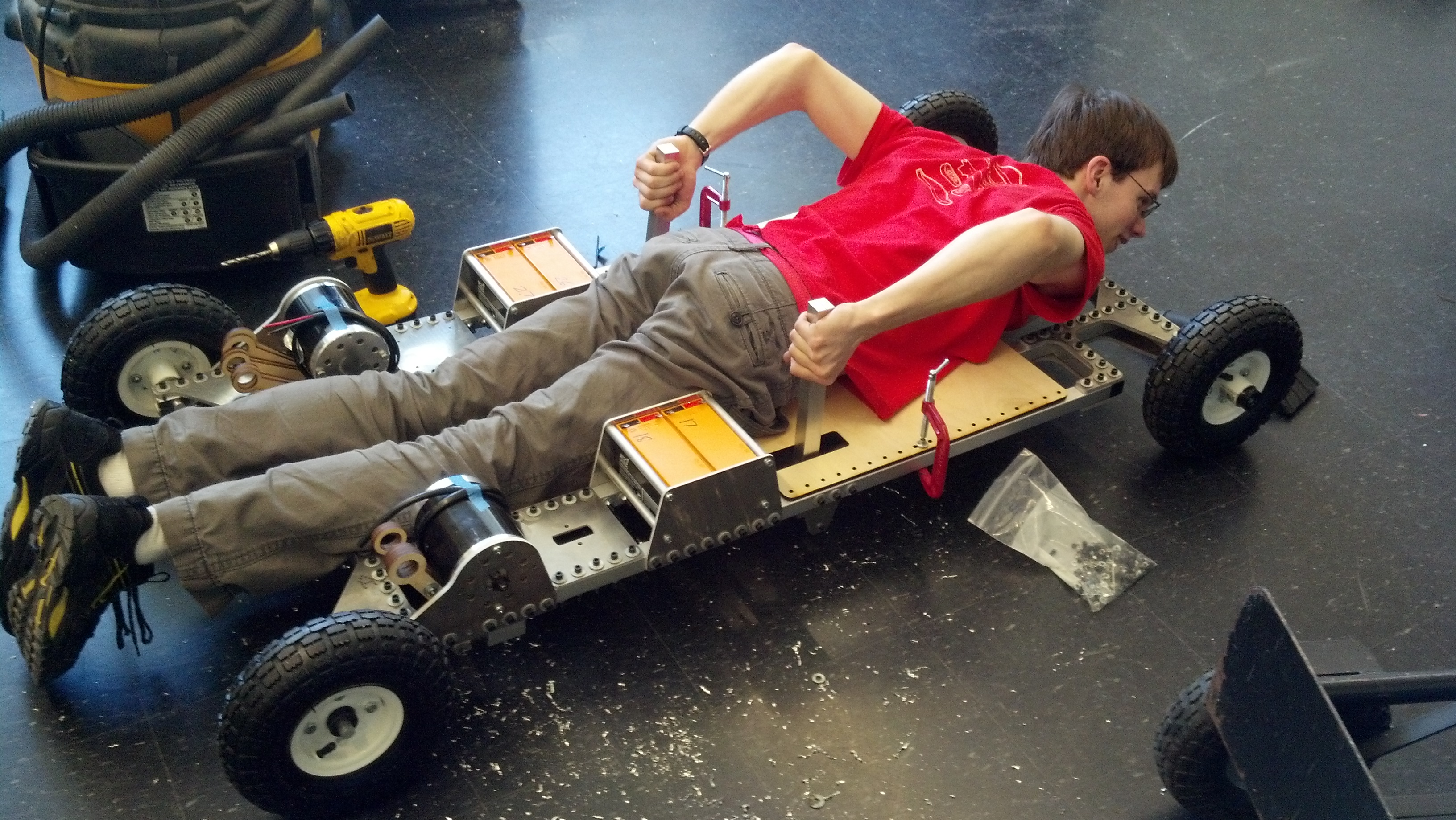
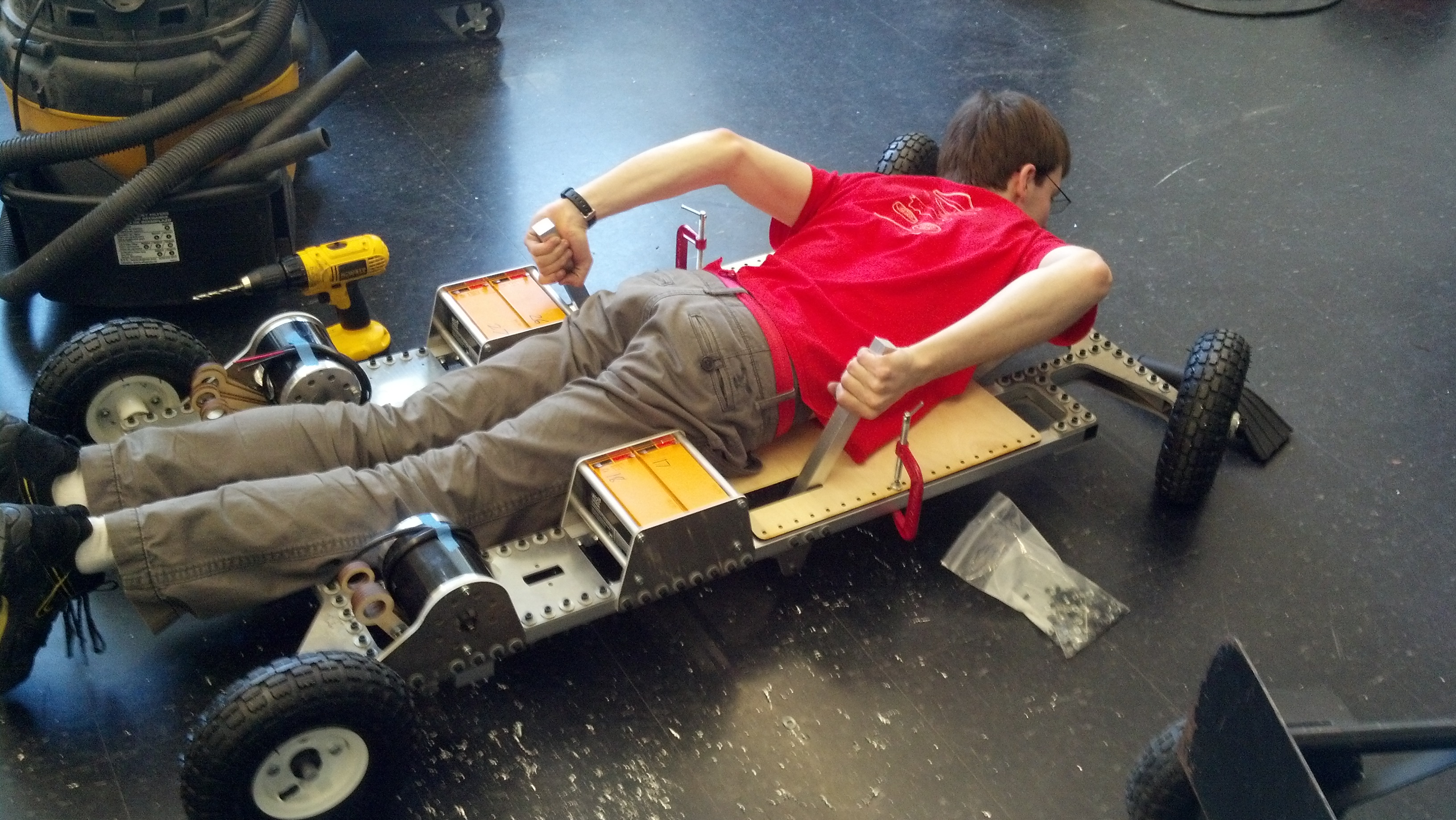
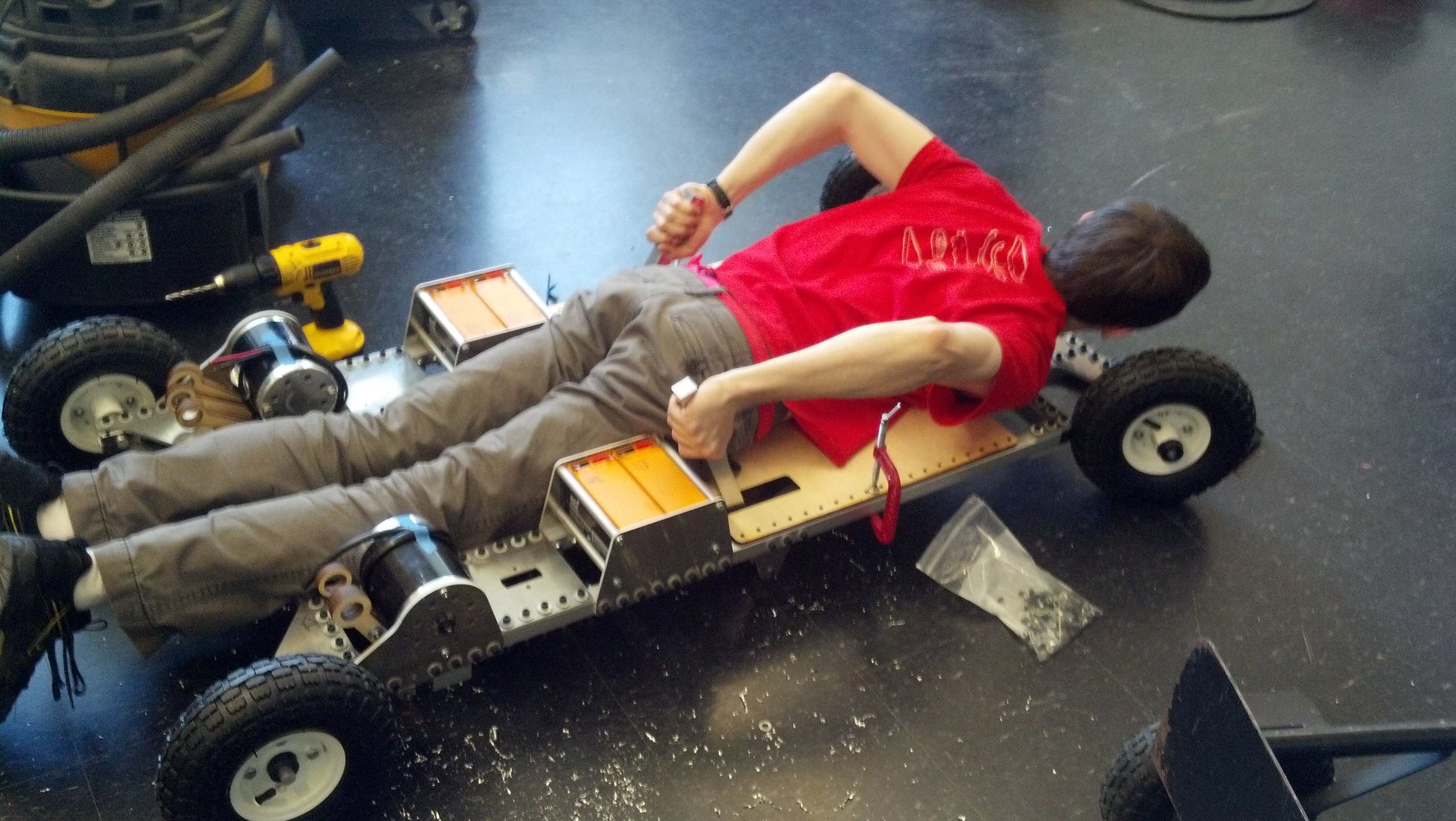
Below, we experimented with various rider positions before settling on a superman-style kart. The rider rests on his stomach with his head facing forward and hands by his sides.
Eric rests on a couch cushion and moves his hands and feet to find comfortable positions for controls.
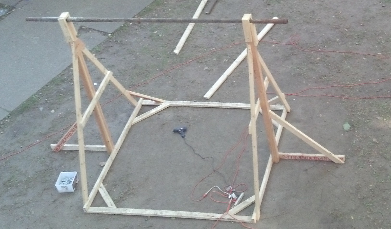
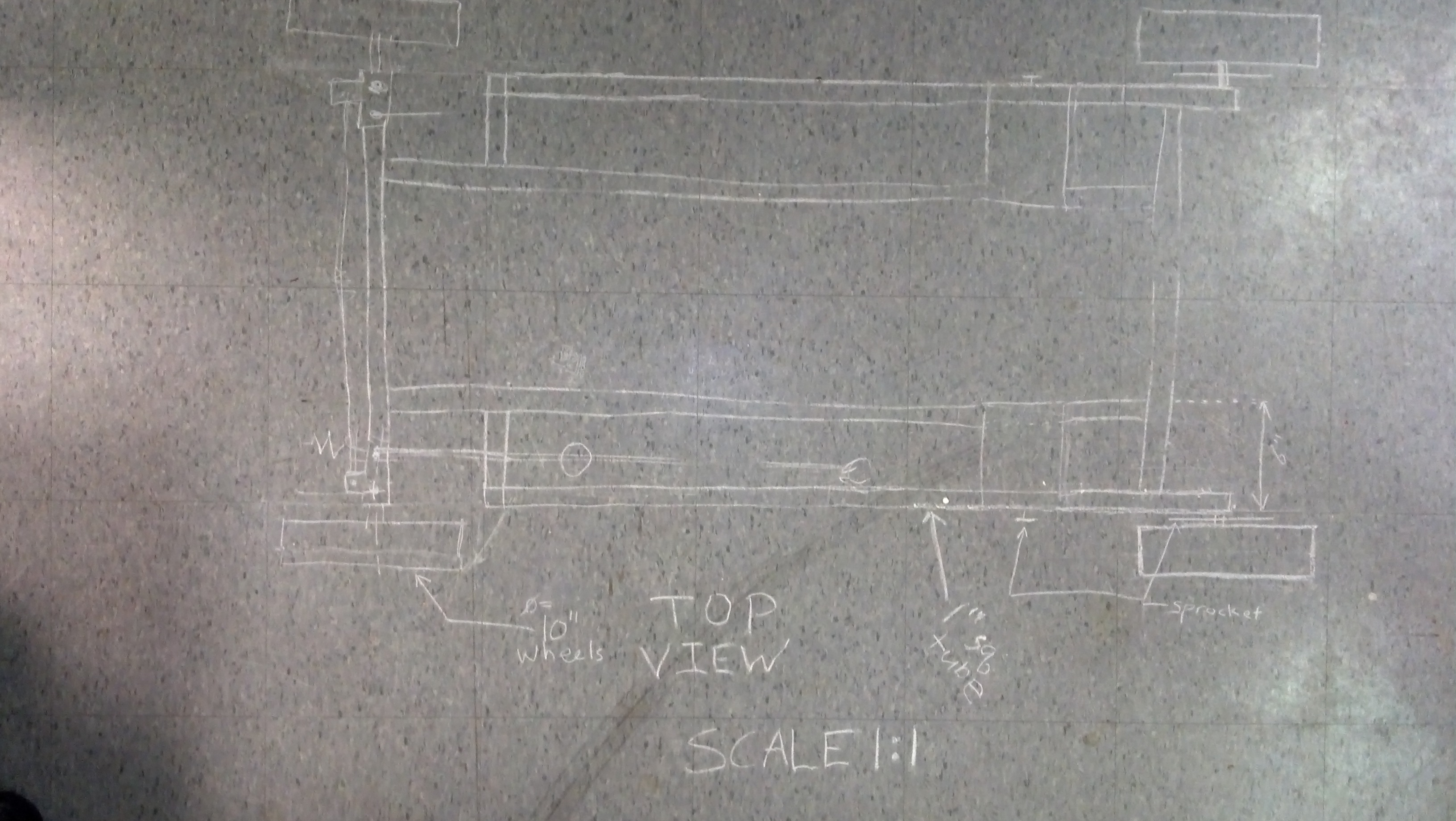
We outlined our design for the kart by drawing on the floor with chalk. Each tile is 1 foot on an edge.
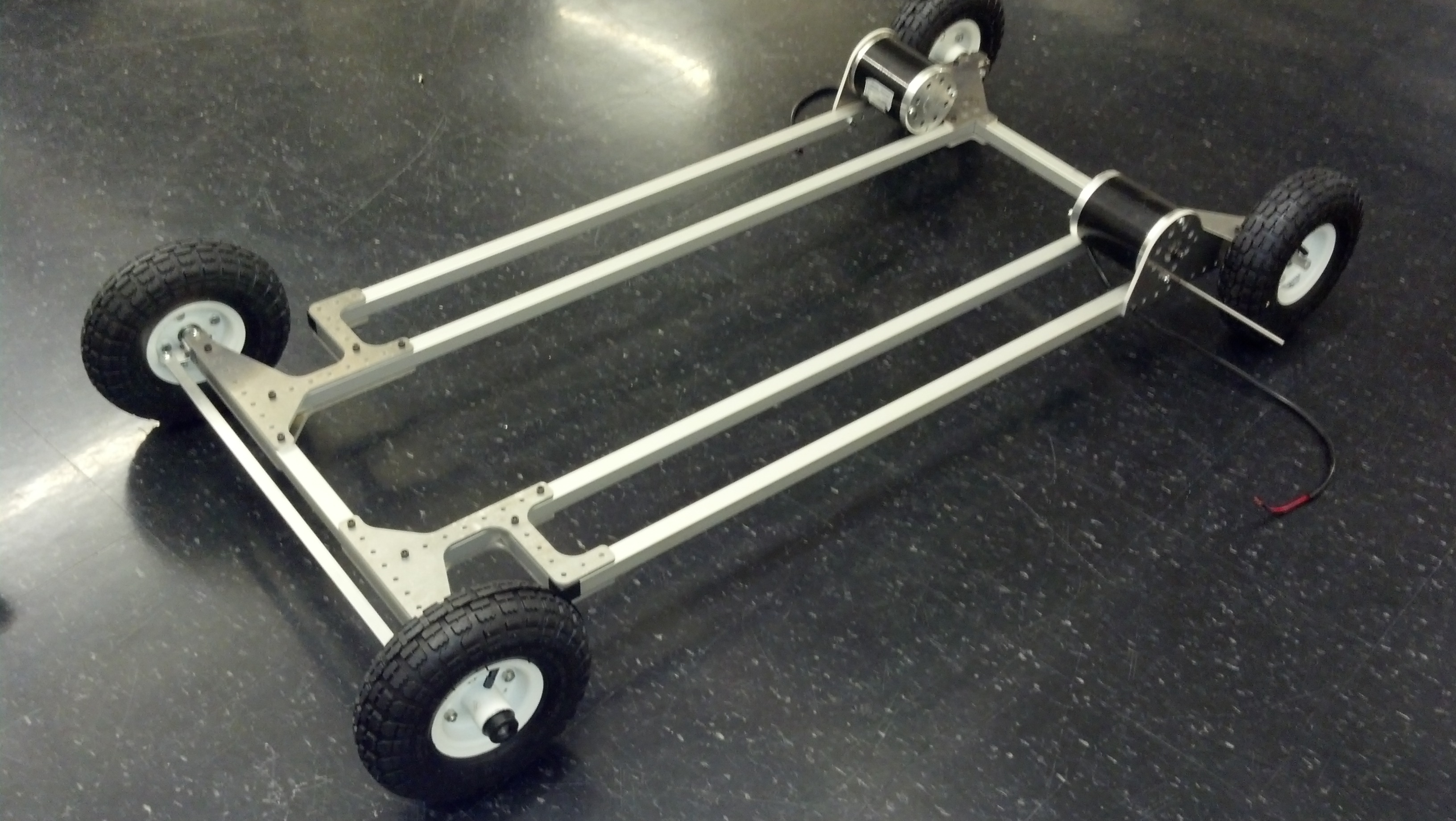
Next, we started designing the go kart in SolidWorks. To collaborate, we set up an SVN repo on which we shared SolidWorks models, pictures, and parts orders. Once we received our first order of parts, we started building the frame. One way we stayed in budget was to use hand-truck wheels from Harbor Freight, which are significantly cheaper than wheels sold on hobby EV sites.
alternatively called ExcessiveScrewHoleKart
We found a cheap supplier of square aluminum extrusion for the frame and joined the pieces with waterjetted aluminum plates.
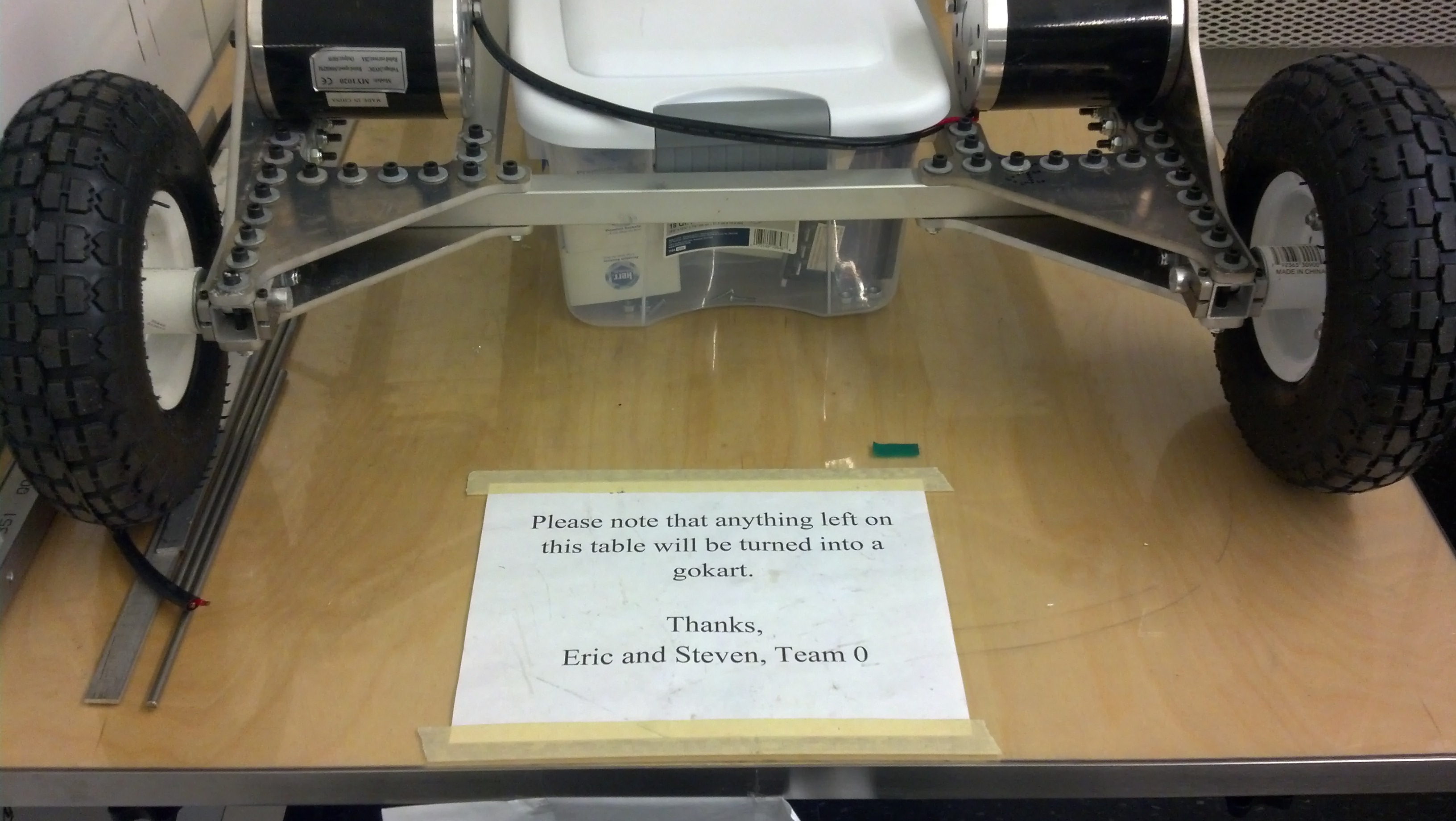
A sign warns fellow students against crowding the workspace with personal belongings.
After the frame, we designed more complicated parts like the brakes and steering. Here are prototype versions of them.
Here are prototype versions of steering and brakes.
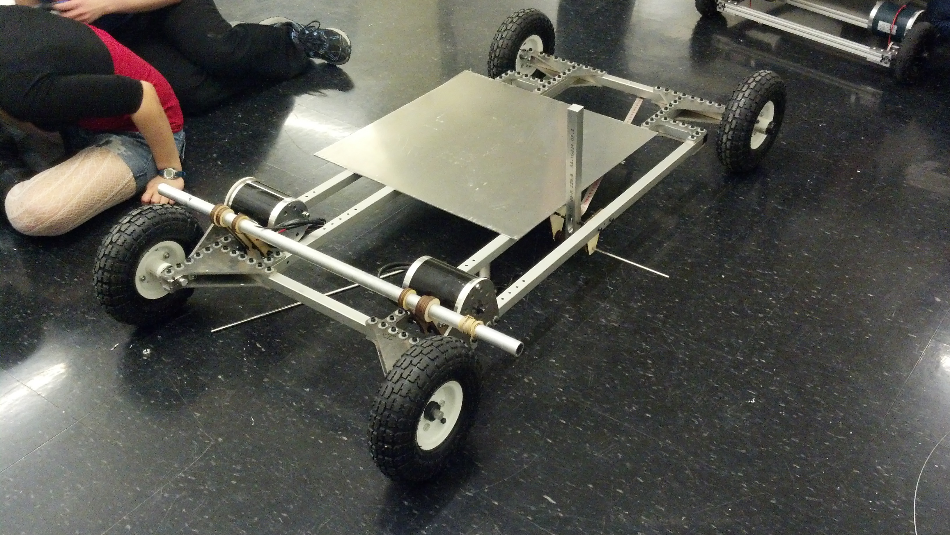
Finally, we finished the steering and started on other mounting hardware, such as battery mounts, the motor controller, and switches.
Eric demonstrates using the levers to turn.
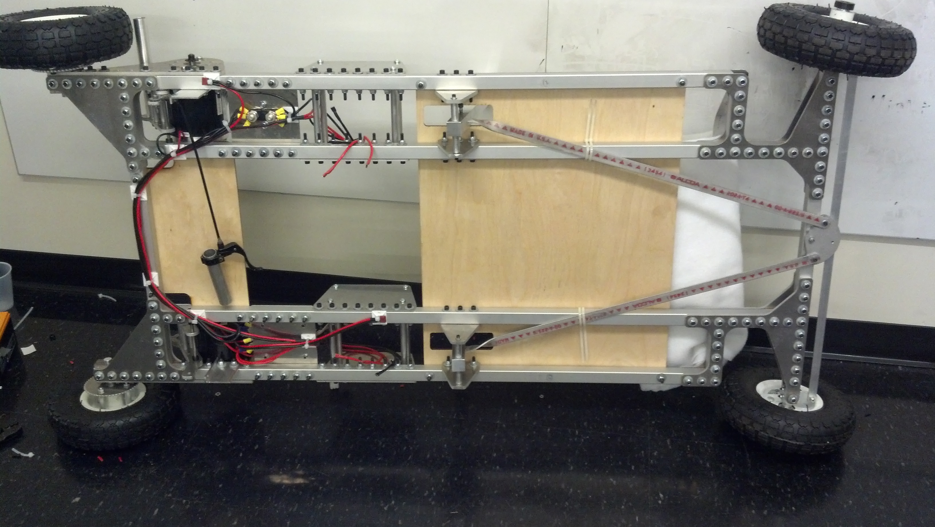
At the end of the build, we wired up the electrical system and installed brakes.
RoachKart is turned on its side to allow access for wiring.
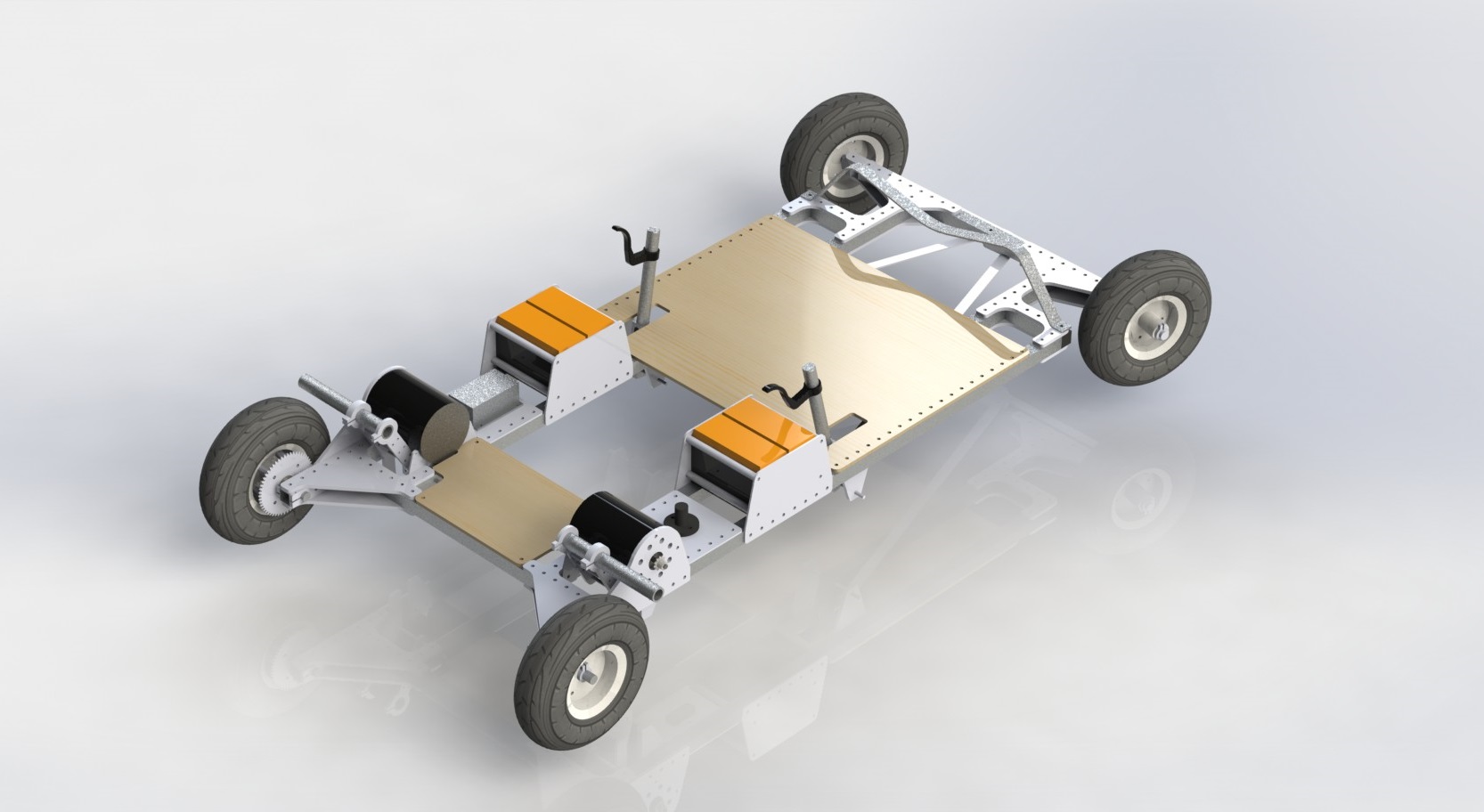
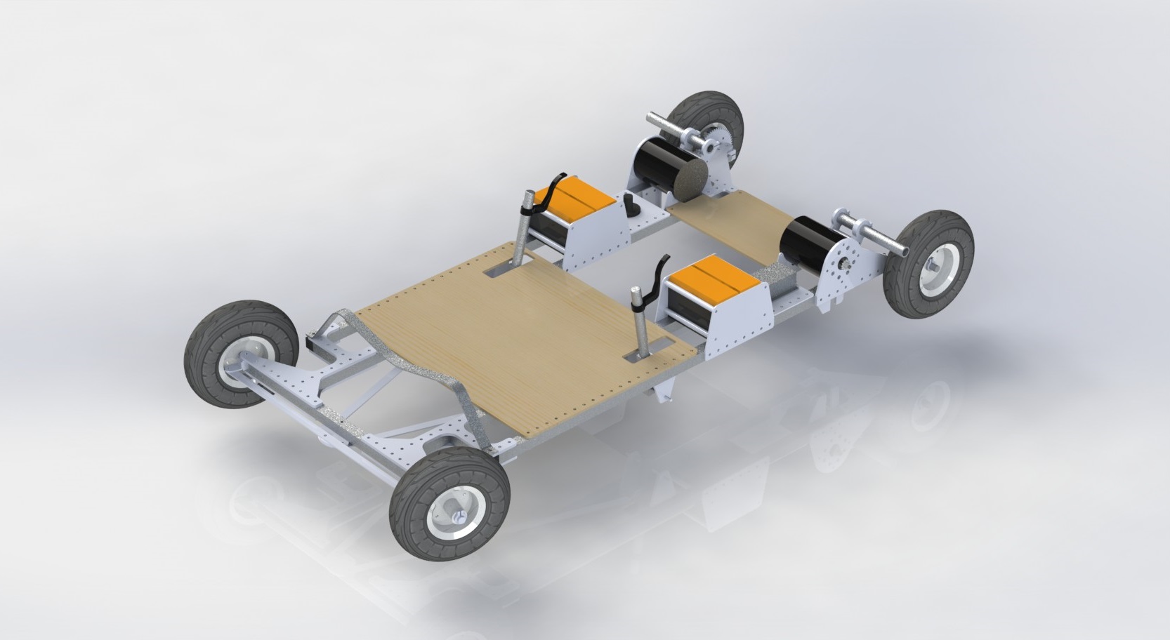
We also added a shoulder rest, white padding for the deck, and a helmet for the rider, all while updating our CAD model to plan what features still needed to be installed.
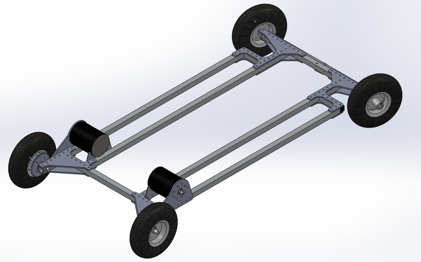
Final CAD rendering shows all major features of the kart except the front cowplow and headlights, which we added on a whim afterward.
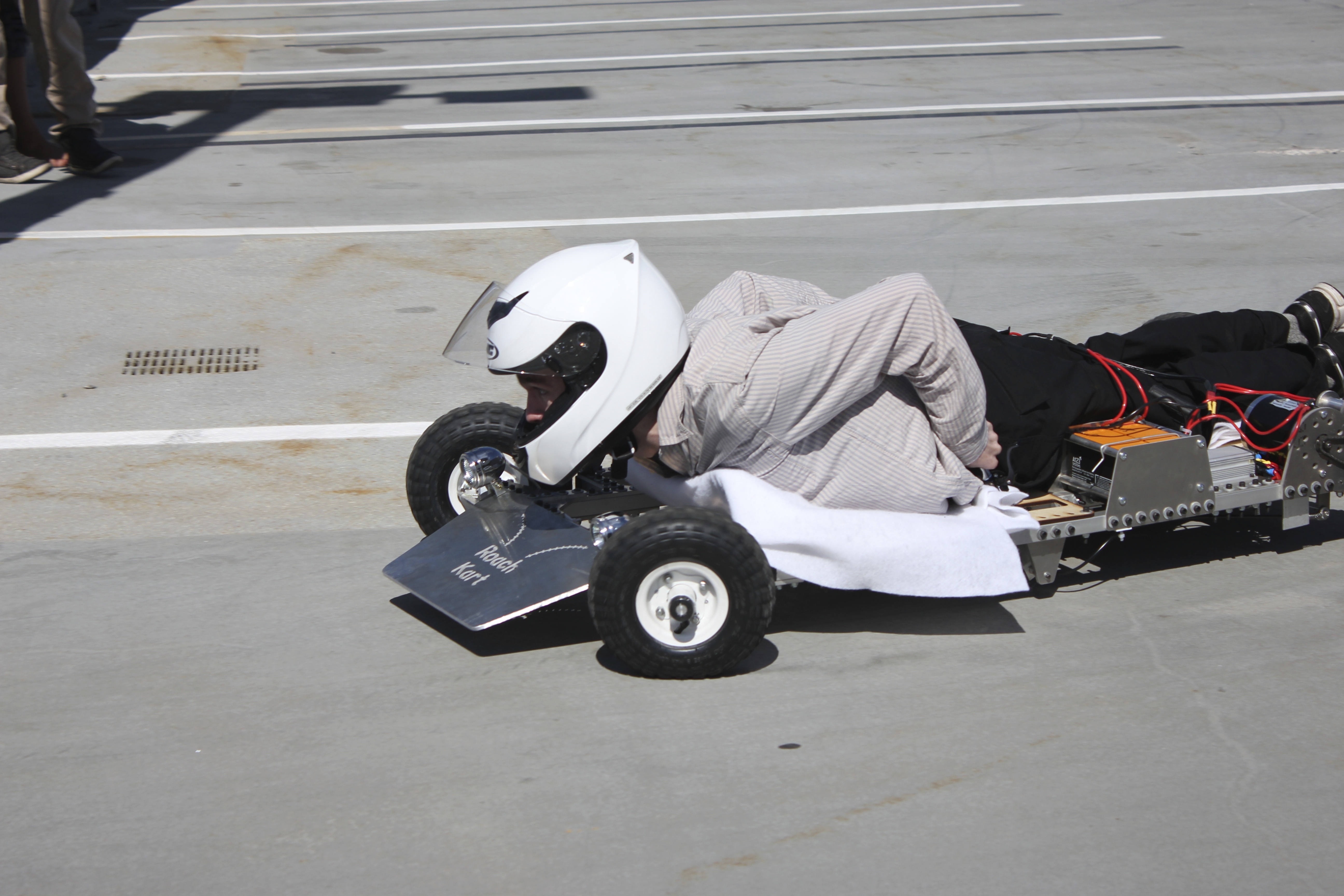
Then, we took it for a test ride. Here’s a video of one of the first times we took RoachKart out. Eric and our TA Banks ride it. You can see here why we named it RoachKart–it’s flat and fast. I like how it has low enough clearance to skit underneath a nearby porch. Without a helmet, RoachKart riders can clear 14″ clearances.
Also, driving so low to the ground is really exhilarating.
In the end, our kart performed well, scoring both a low time in the final drag race and a low score in the parking garage hill climb, which measured a composite of speed and vehicle efficiency. At our best, our kart went 50 meters in 7.00 seconds starting from standstill.
The kart climbs to the top of a parking garage and races across the finish line. Photo by Kirsten L
As far as improvements, the biggest thing we would improve if we had time would be the brakes. We implemented scrub-style brakes with a piece of aluminum pressing against the tires, but we suspect disc-style or drum-style brakes would be more effective. In addition, the steering linkages, which were made from 1″x1/8″ aluminum extrusion, could also be improved to bend less in compression. However, for the amount of time we drove the kart, we found that the slop that this contributed to the steering was negligible.
Anyway, there’s lots of go karts that got built, but we think our kart is the most fun to ride.
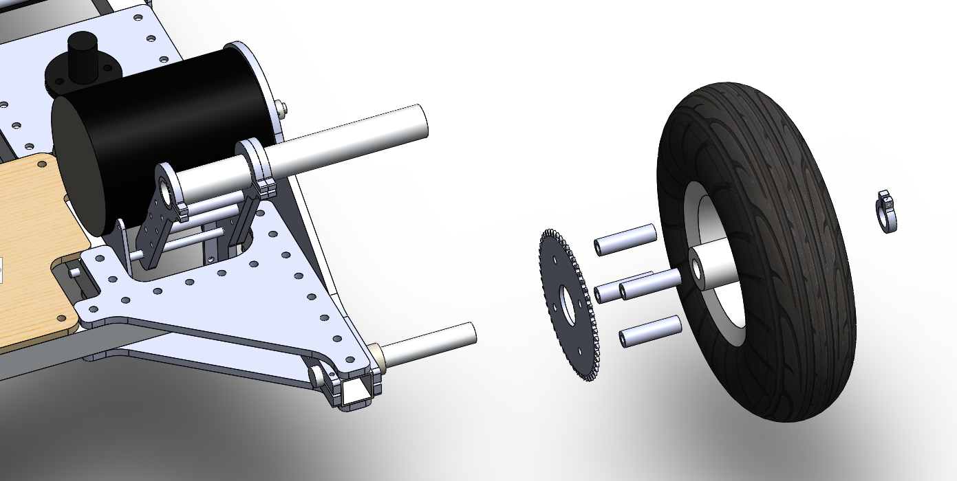
Edit: Someone asked about the rear assembly, so here’s an exploded view!
Shown here is the rear assembly including the motor, motor mount, rear axle, a clamp on the frame that fixes the rear axle, and the wheel sprocket assembly. The wheel sprocket assembly is exploded.
For the rear drive, we waterjetted some large sprockets from aluminum and slightly beveled the edges with a sander. Then, we and then bolted them to the side of the wheels we bought from Harbor Freight, standing them off with spacers. The wheels already had bearings in them, so we simply clamped down the rear axles and slid them on. We also added a clamping collar on the outside of each rear axle to keep the wheel assemblies from sliding off. The sprockets on the motors were also waterjetted, and we screwed them into clamping collars and clamped them onto the motor shafts. We then attached chain (not shown) around the sprockets.
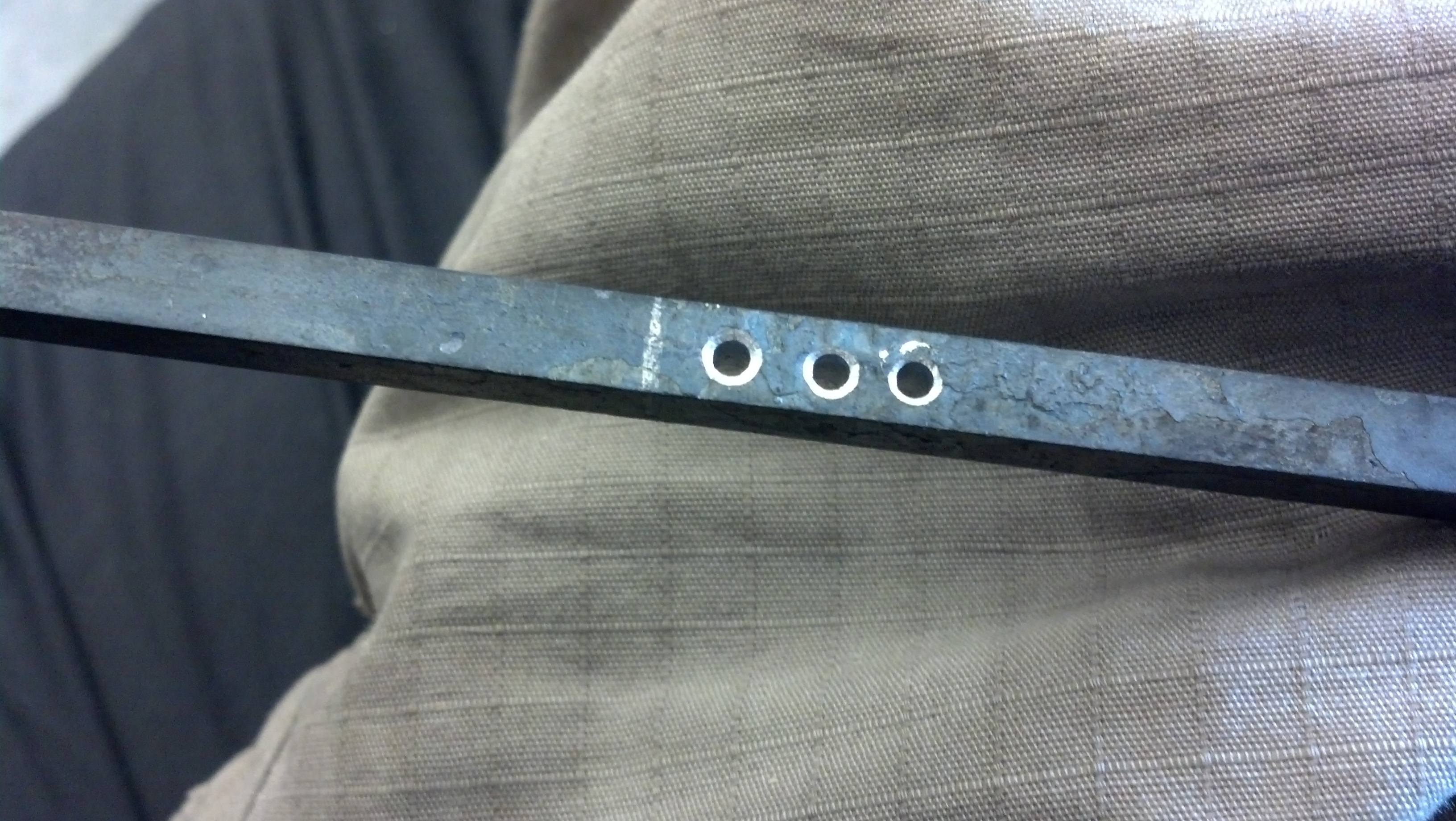
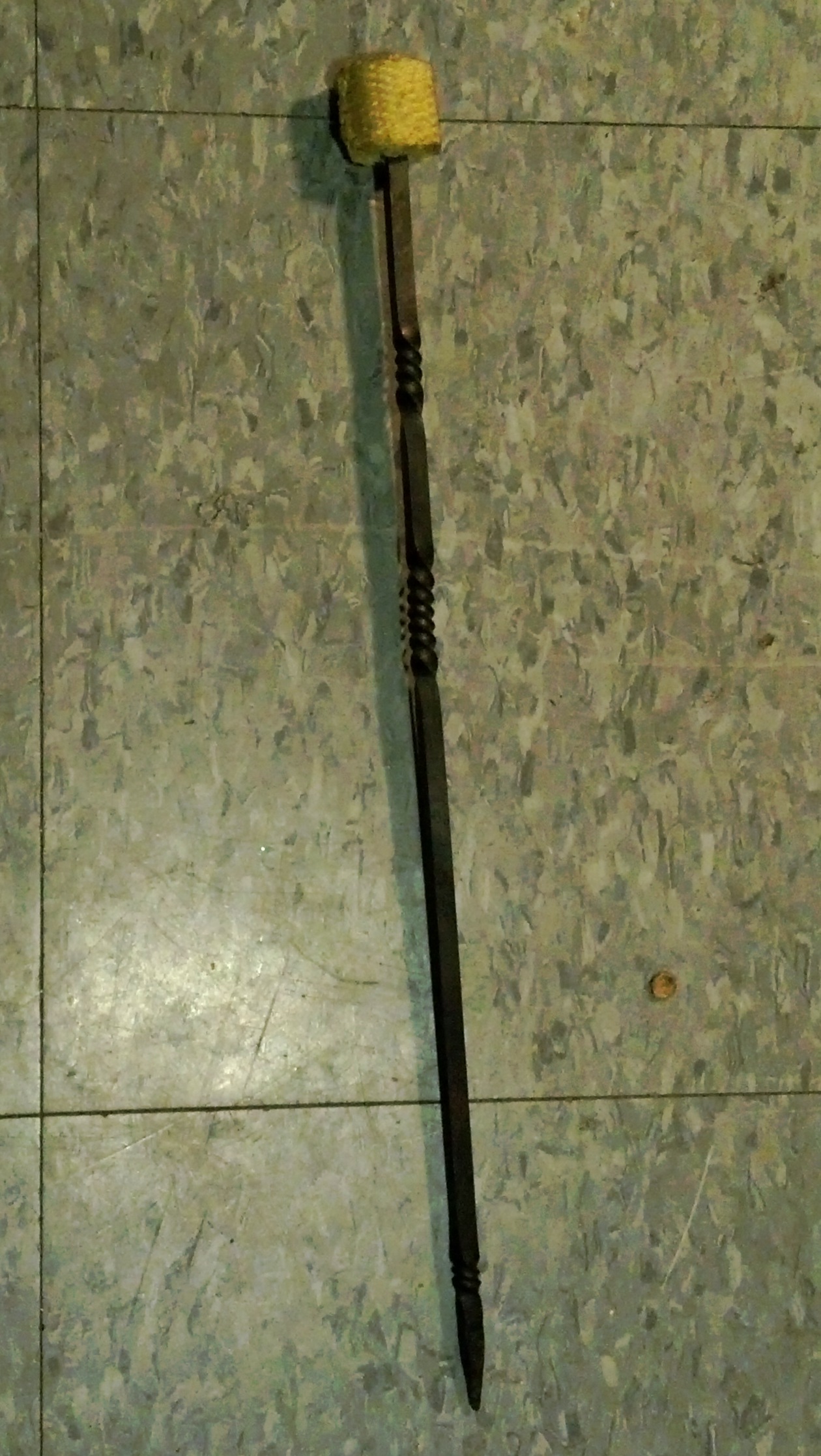
I made a torch! It’s got a decorative twist, which I saw on torches like those sold here.
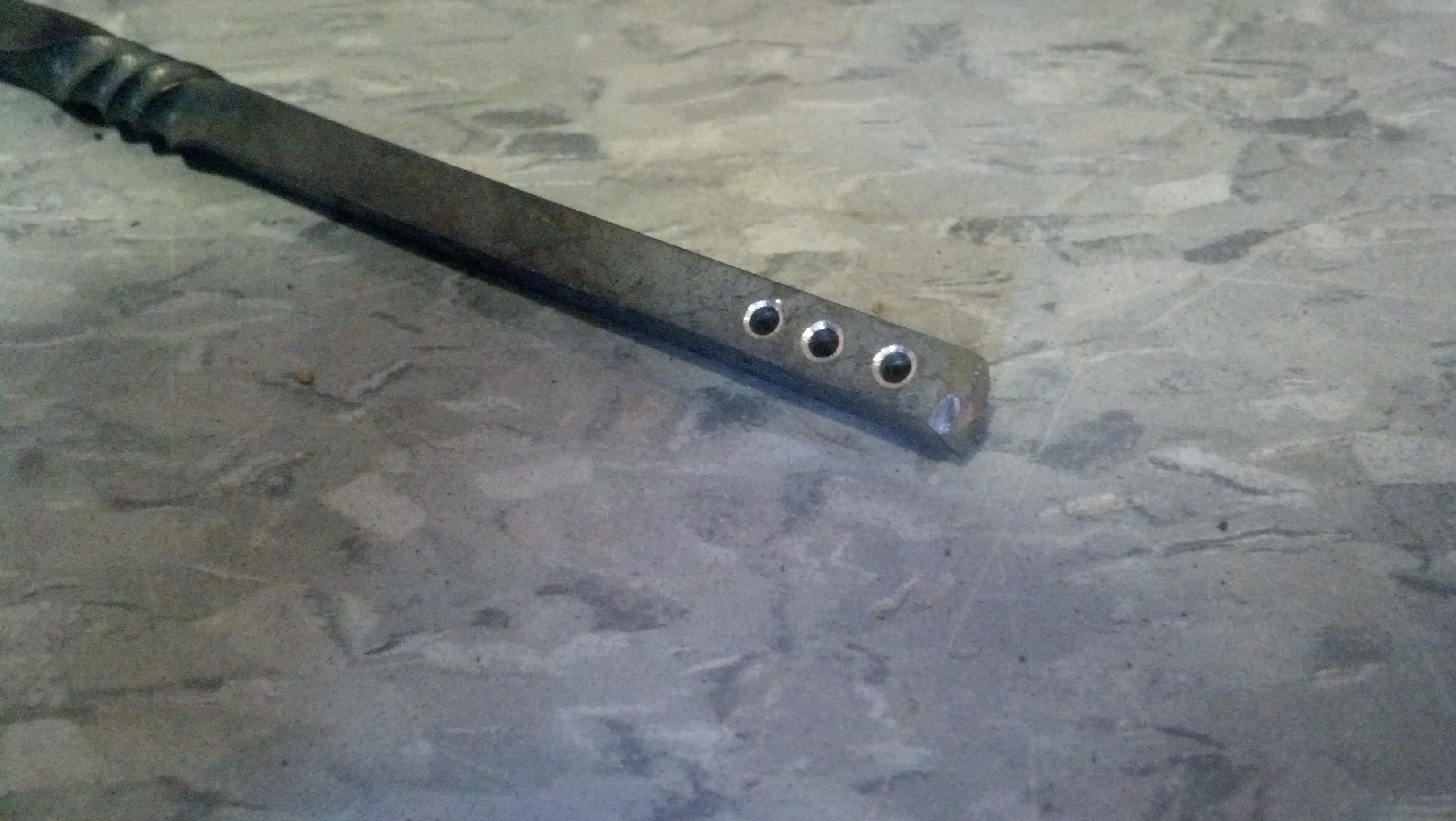
First, I drilled 3 holes in some 1/4″ iron stock. Their purpose comes later.
. . .
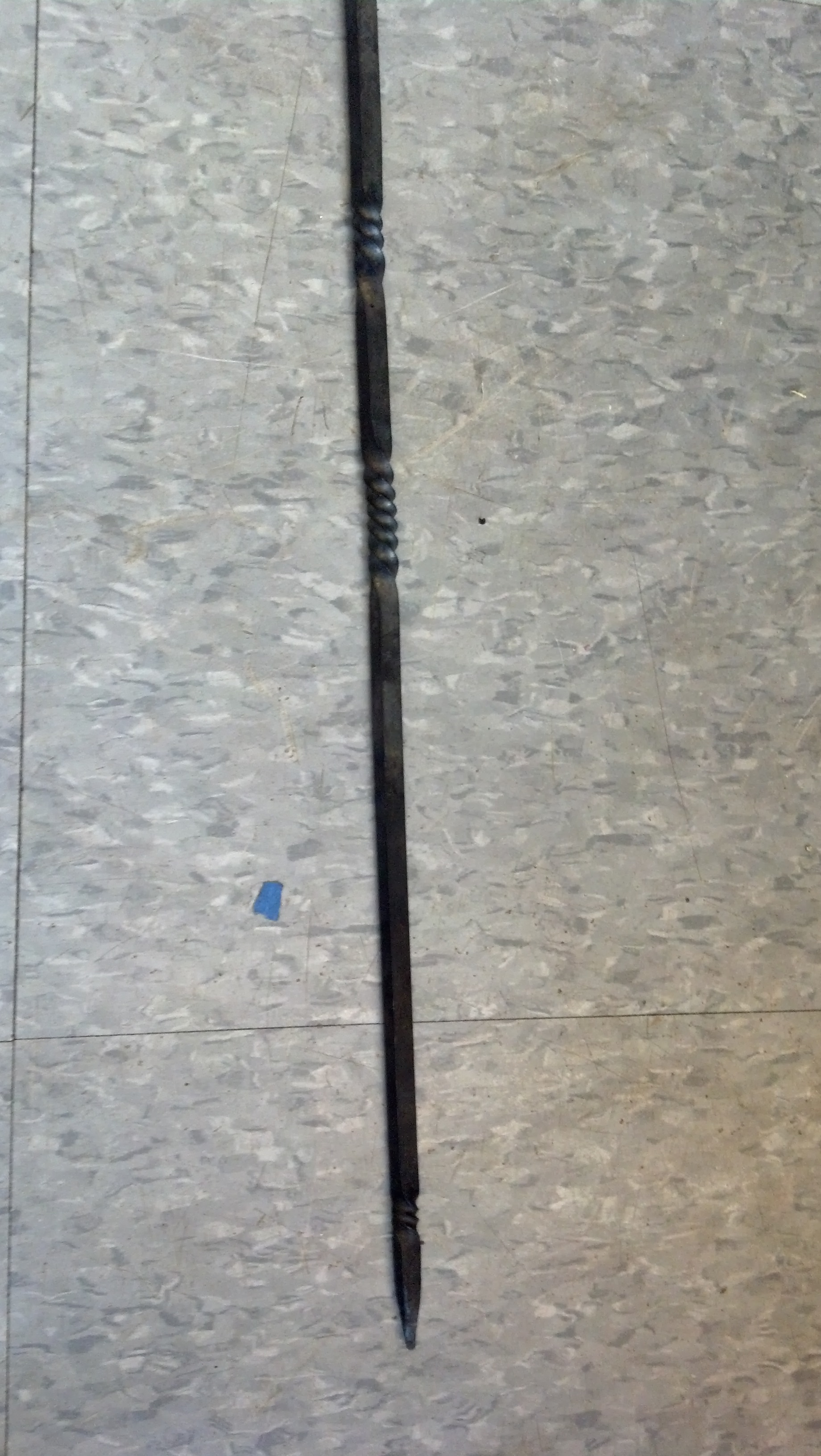
Then, I heated the iron in a forge, tapered the end, and added 3 twists. I learned how to do this in MIT’s blacksmithing seminar. After this, I cut the stock to about 15″, ending at the series of holes.
Adding twists requires heating a short section of the iron and possibly quenching the adjacent areas with water to limit the length of the twist.
I cut off the extra stock with a cutoff wheel.
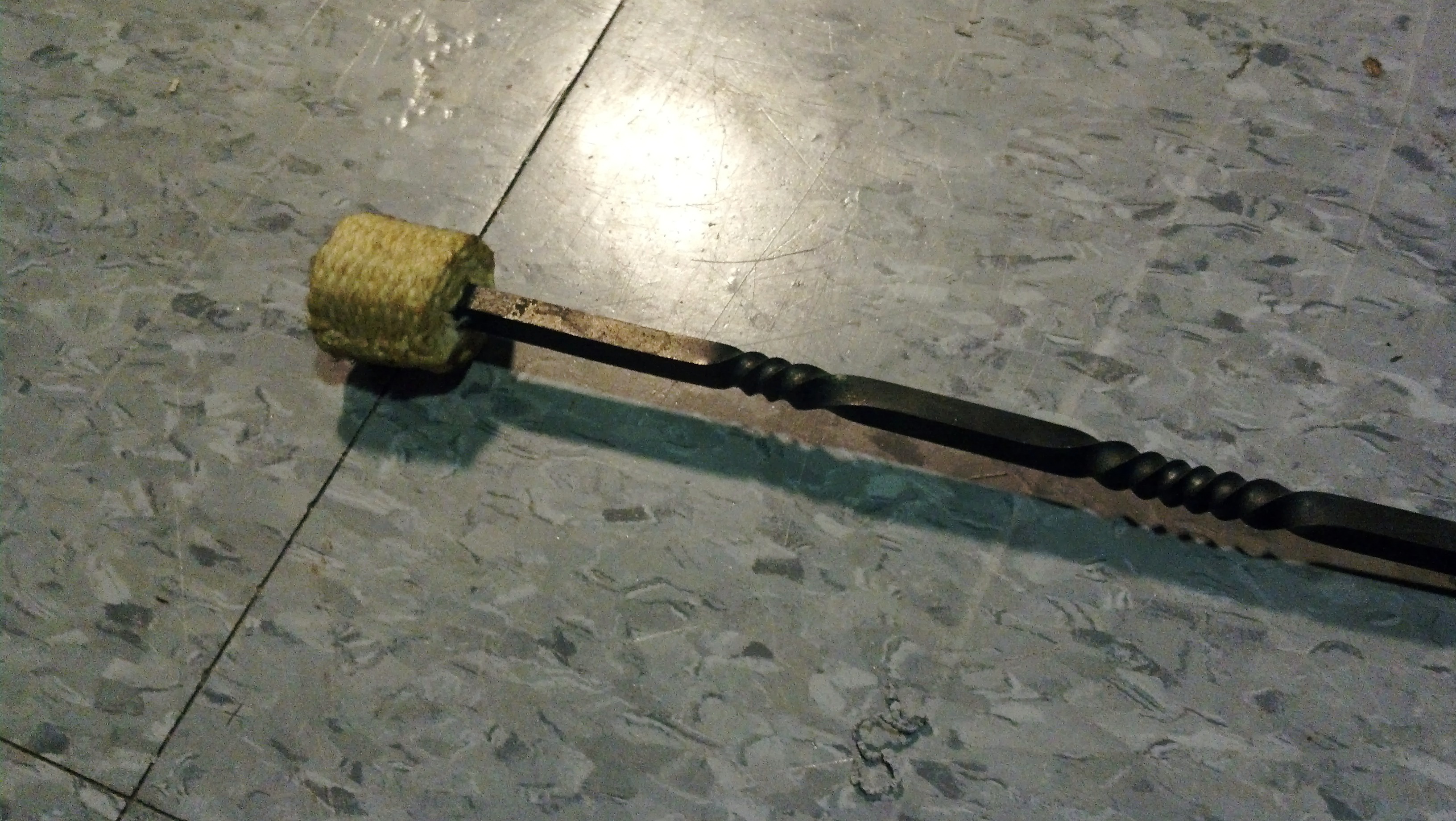
Next, I added about 9 inches of 1 inch kevlar wick to the end. I used a needle to sew a few meters of kevlar thread through the wick and through the holes to secure the head.
I used a straight needle to sew through the wick and the holes at the beginning. Then, I used a curved needle to sew through the wick.
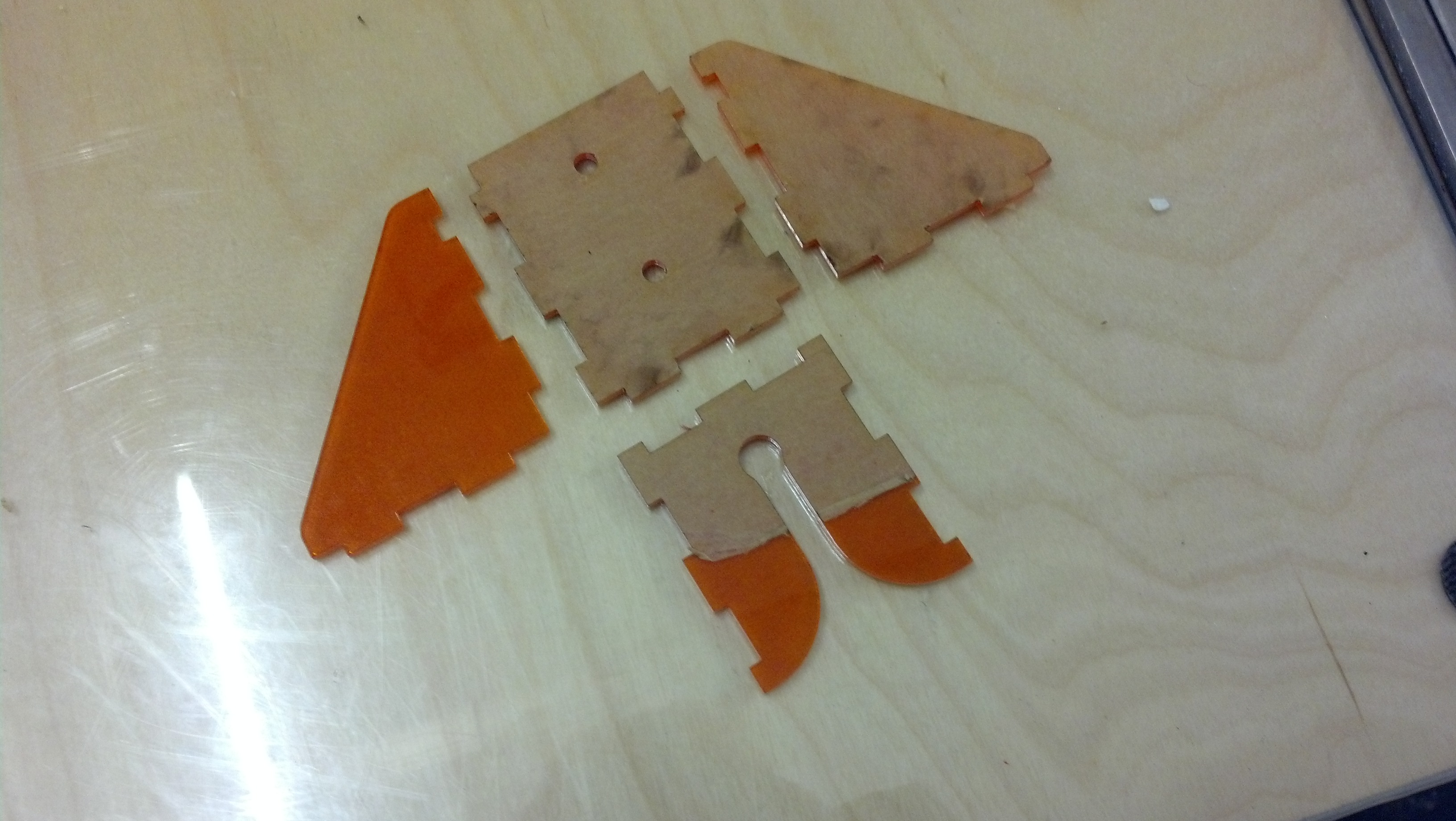
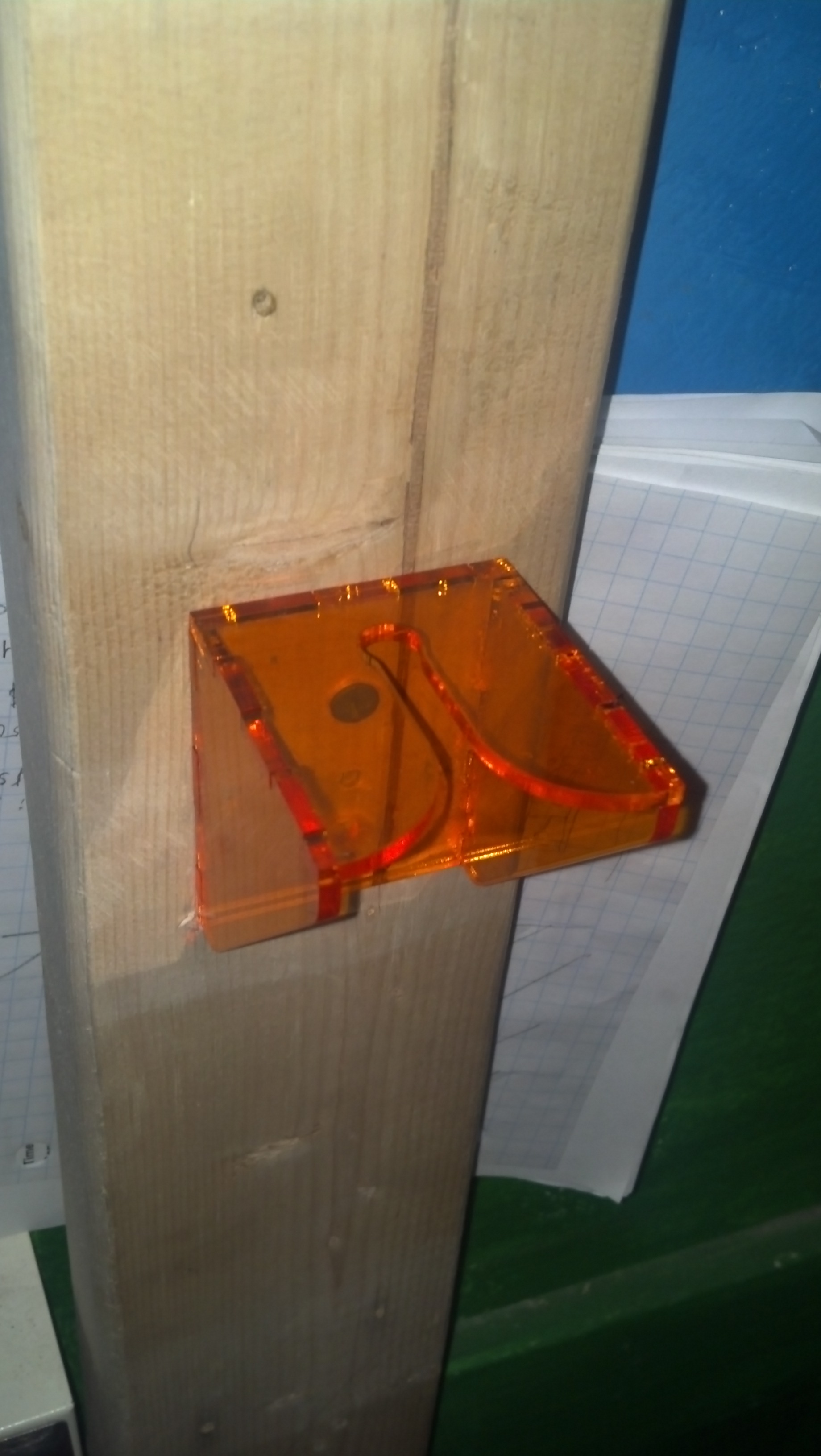
I cut a sock poi holder out of acrylic. It’s a slot with a curved, tapered opening, so it’s easy for poi to slide in to hang and slide out. First, I made a holder out of cardboard, but then I cut some out of acrylic, which resulted in a slot that is a much smoother and less likely to catch.
Here are the acrylic pieces. I set the design a few thou large to account for the laser kerf as noted in Charles’s guide.
Here are the pieces prior to assembly.
The holes in the back are for screwing mounting the holder.
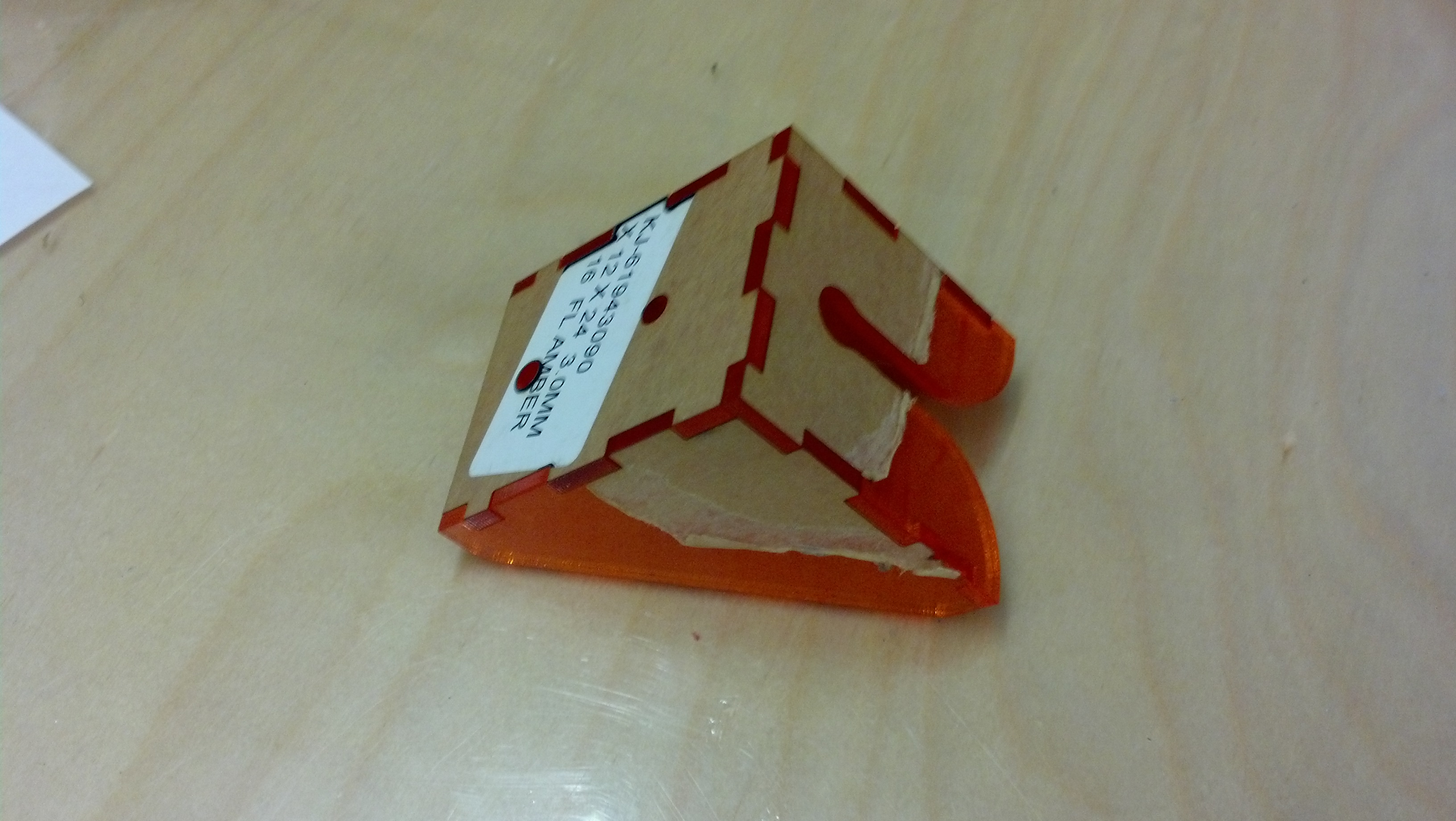
Then, I assembled them and fused them with cyanoacrylate glue.
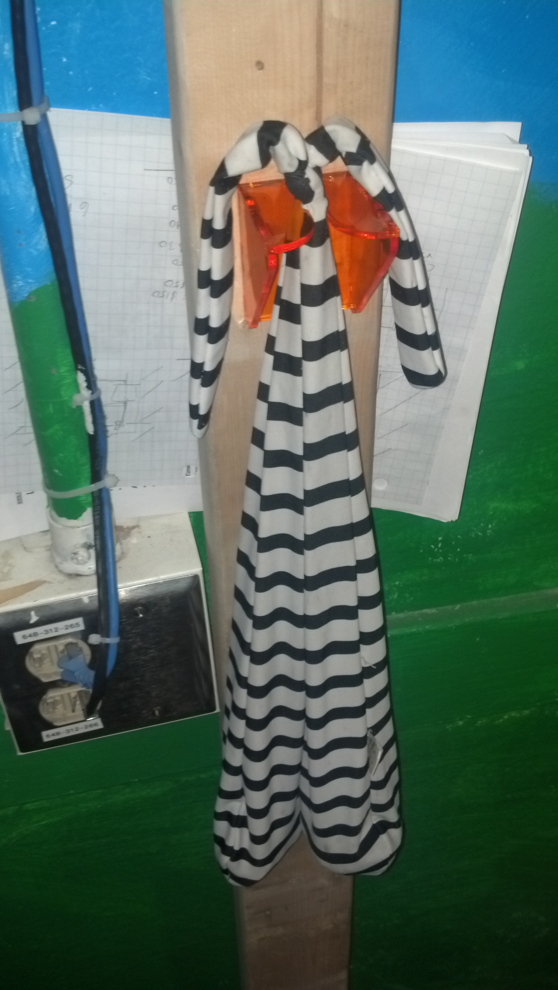
Wood screws secure this piece against a 2×4.
The color is great.
Other Stuff
I also prototyped a mount for an optical quadrature encoder and a mount for a robotic radiator dial controller, but I’ll post about those later.
Laser cutters are really sweet! You just put your material in, and then you wait a few seconds, and you’ve machined this really complicated part. Here’s some stuff I made using a laser cutter over the past year.
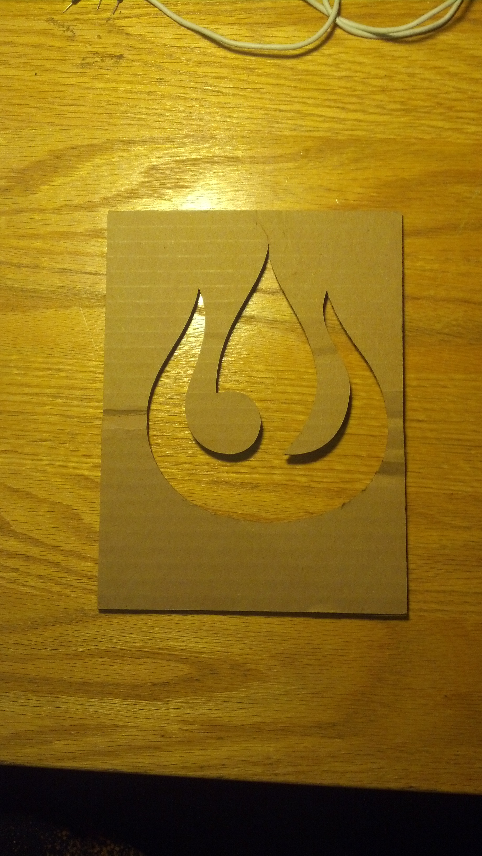
Stencil for Bleaching a Shirt
My friend Kirsten L. gave me this idea and helped me make stencils for making bleached T-shirts. Here from Make and here from Stencilry are instructions for making T-shirts with cool graphic effects using bleach and a stencil. However, instead of making a stencil by hand, I used a laser cutter, which was really easy. I didn’t use very complex designs, but a laser cutter would be way preferable compared to hand cutting for very intricate stencils.
This stencil was cut from cardboard using a laser cutter.
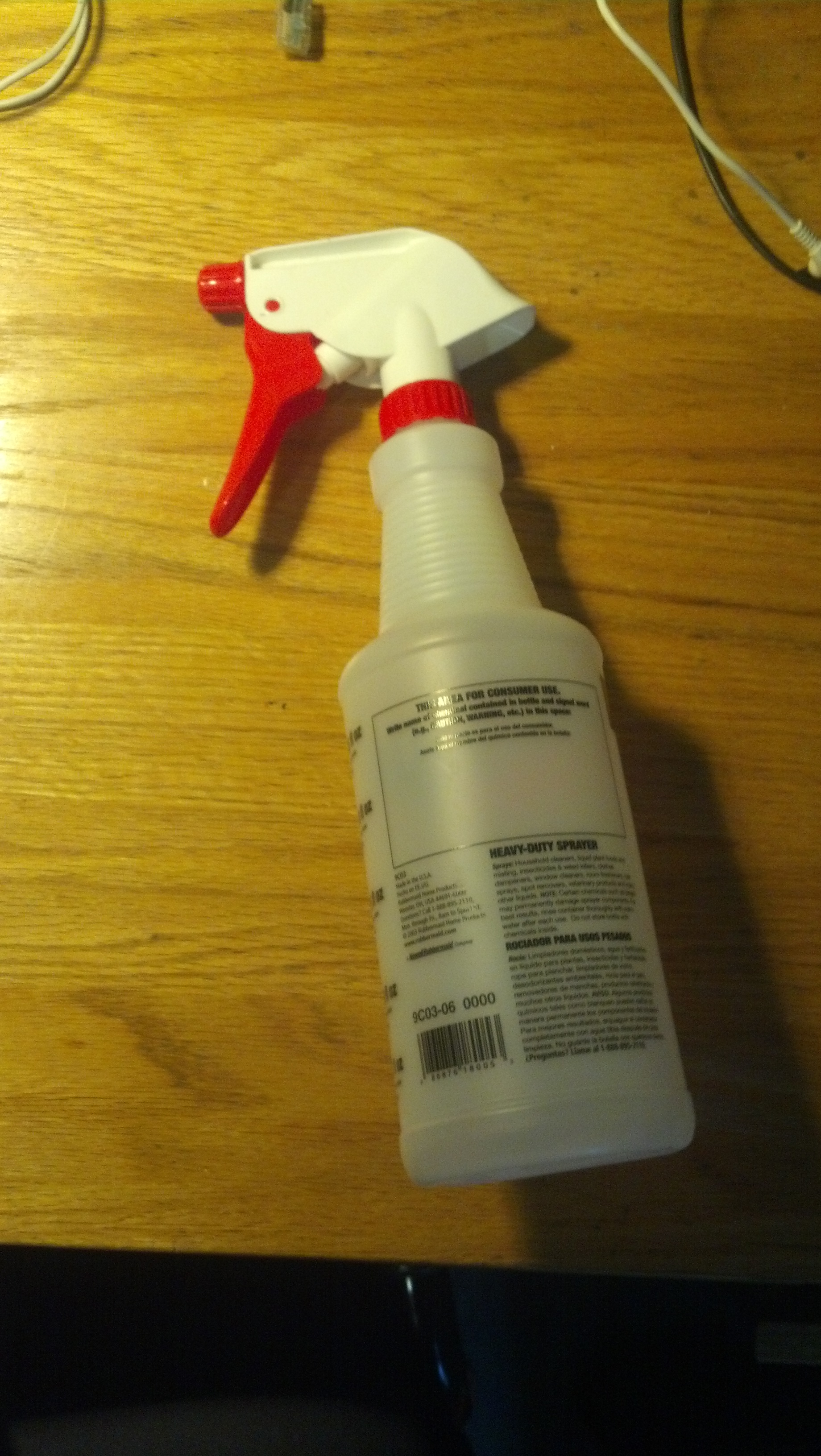
I mixed and sprayed bleach using a spray bottle.
Here’s one with a fire nation symbol. whooo fire.
Here’s my shirt!
I also made another shirt. In my next post I’ll tell you about something else I made with a laser cutter.