This IAP, I worked with a team of 5 undergrads to build an awesome robot that competed autonomously in a ball-collecting game at the end of January.
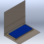
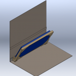
When we started designing our robot and strategy, we focused on simplicity and high ball capacity. To this end, our robot consists primarily of a wide tread belt. This single mechanism pulls in balls, drives them to the top of the robot, and deposits them to a hopper before a gate opens to unload them. We also favored the wide channel of this design over designs that moved balls through a single-file bottleneck. We named our final product EARL, the “Electronic Assistant Research Labrador”.
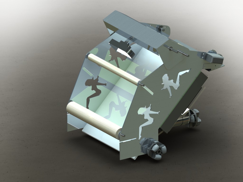
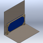
This rendering made by team member Fred M. is taken from our team journal. The black tread is omitted in this rendering, so the wide ball channel is visible below the rollers.
For the code, we used python to implement a state machine that encoded various behaviors. For example, EARL used IR sensors mounted to either side of the conveyor belt to perform wall following to move around the field. Meanwhile, EARL used the camera above the belt to search for red or green balls. For the vision, we used the opencv library.
Beyond the idea of a big tread, we also implemented some cool lower-level things. I worked a lot on programming and electronics, so here are some components I worked on or found neat.
Omni Wheels
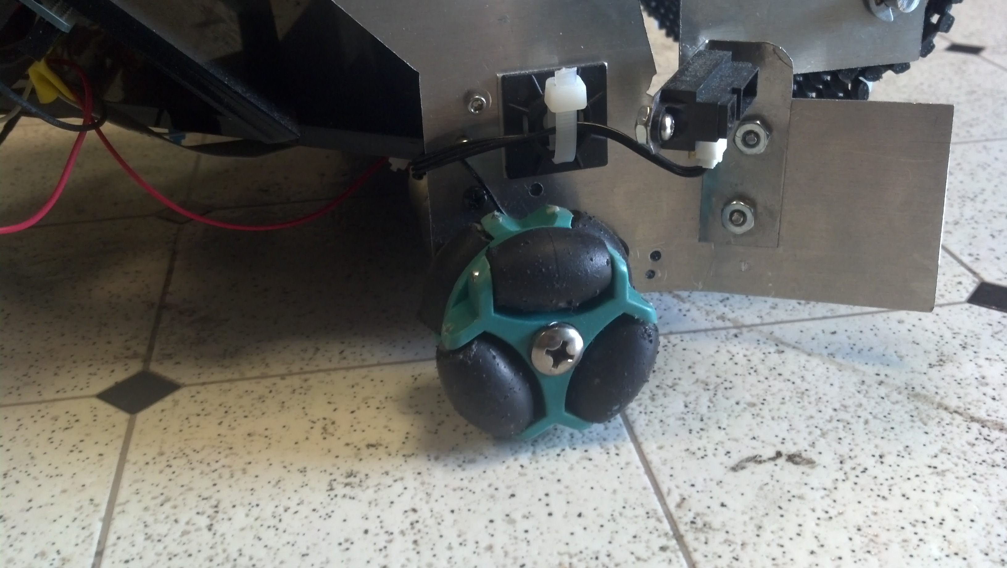
3 omnis, each with 6 black roller wheels make EARL a true 18-wheeler.
From the start, we decided to drop omni wheels onto our robot. Besides looking cool, we liked them because they gave us the ability to strafe along a wall. This would allow us to play defensively, riding alongside the yellow scoring wall to block our opponents. However, we ran out of time to implement this behavior, and gameplay didn’t end up being fast enough at the end game to necessitate this tactic.
Originally, our the rollers on our omnis were a smooth surface, but this proved to be too little friction to drive effectively. Consequently, we coated the rollers in a mix of rubber paint and sand, which significantly increased our traction.
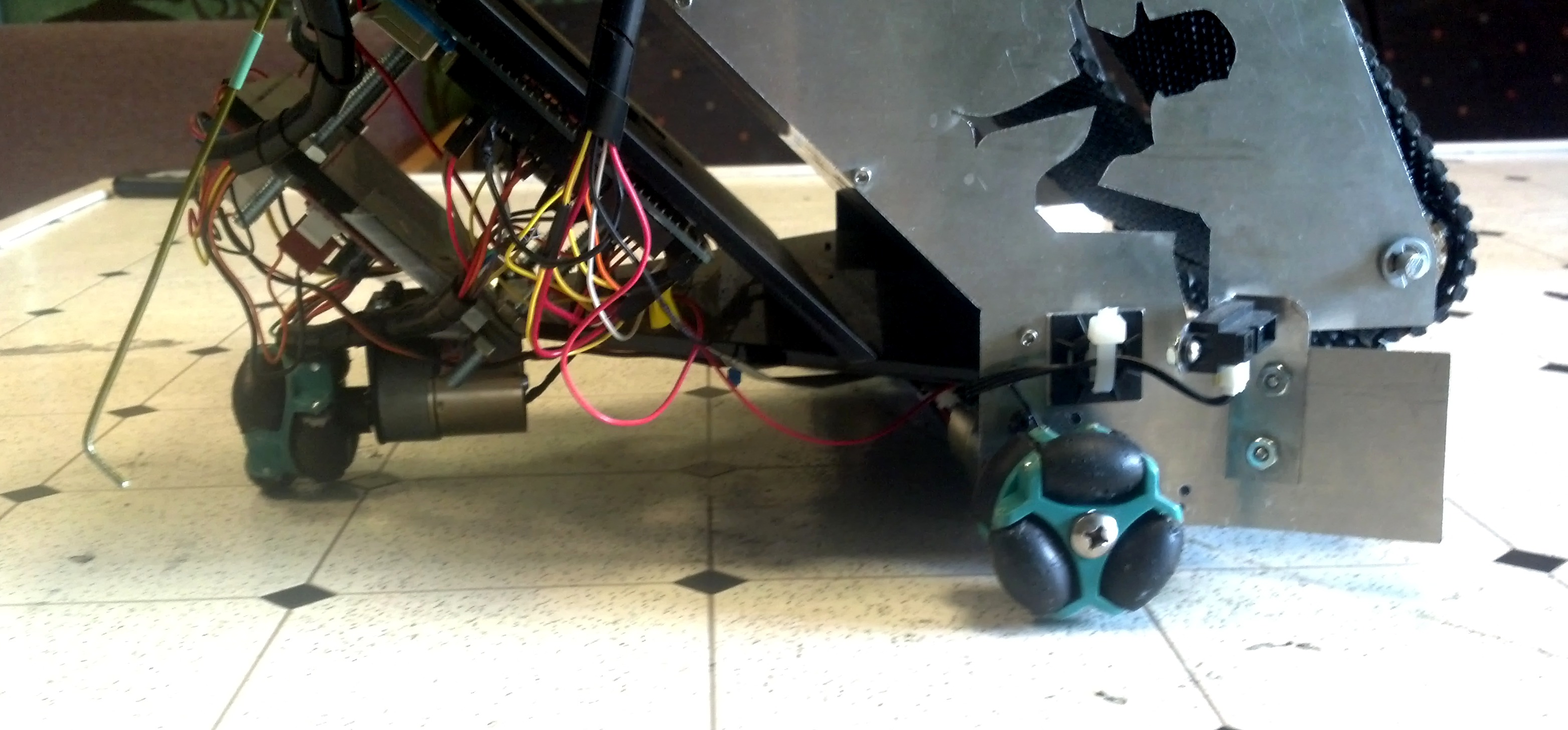
Trucker ladies in the front, omnis on the bottom, and the end of a whisker switch are visible in this side view of the robot.
As a programmer, I also think omnis are fun to program for because they allow for holonomic drive, which I played around with back in FIRST Robotics. The freedom to locomote in any direction in the plane is really convenient. You wanna get somewhere specific? You just do it. For example, my high school team and I made this cute robot that uses a holonomic drive system to align with a feature on a playing field wall.
Lights
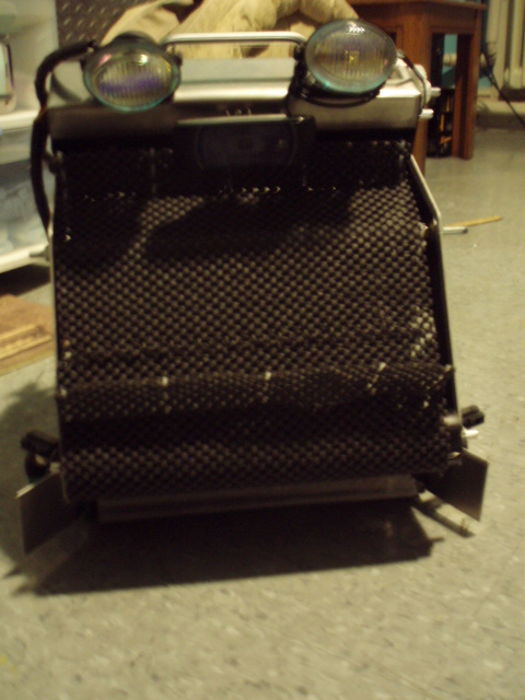
The headlights are visible in the top of the robot. Photo c/o Fred M.
Mounted atop the metal frame, the headlights are a distinguishing feature of our robot. We put them on in the hopes that they would illuminate the field, creating a more even image for processing, but they ended up creating a confusing gradient, so we powered the lgihts off during matches. On the plus side, they contributed significantly to our trucker theme!
On the other side of the robot is a dashboard with switches and LEDs. The switches power on the robot’s logic, main power, and lights, and some of the LEDs show the state of the power systems and batteries. The remaining LEDs indicate the charge on our robot’s onboard flux capacitor, which was tricky to measure, but we were able to do after importing the python module random.
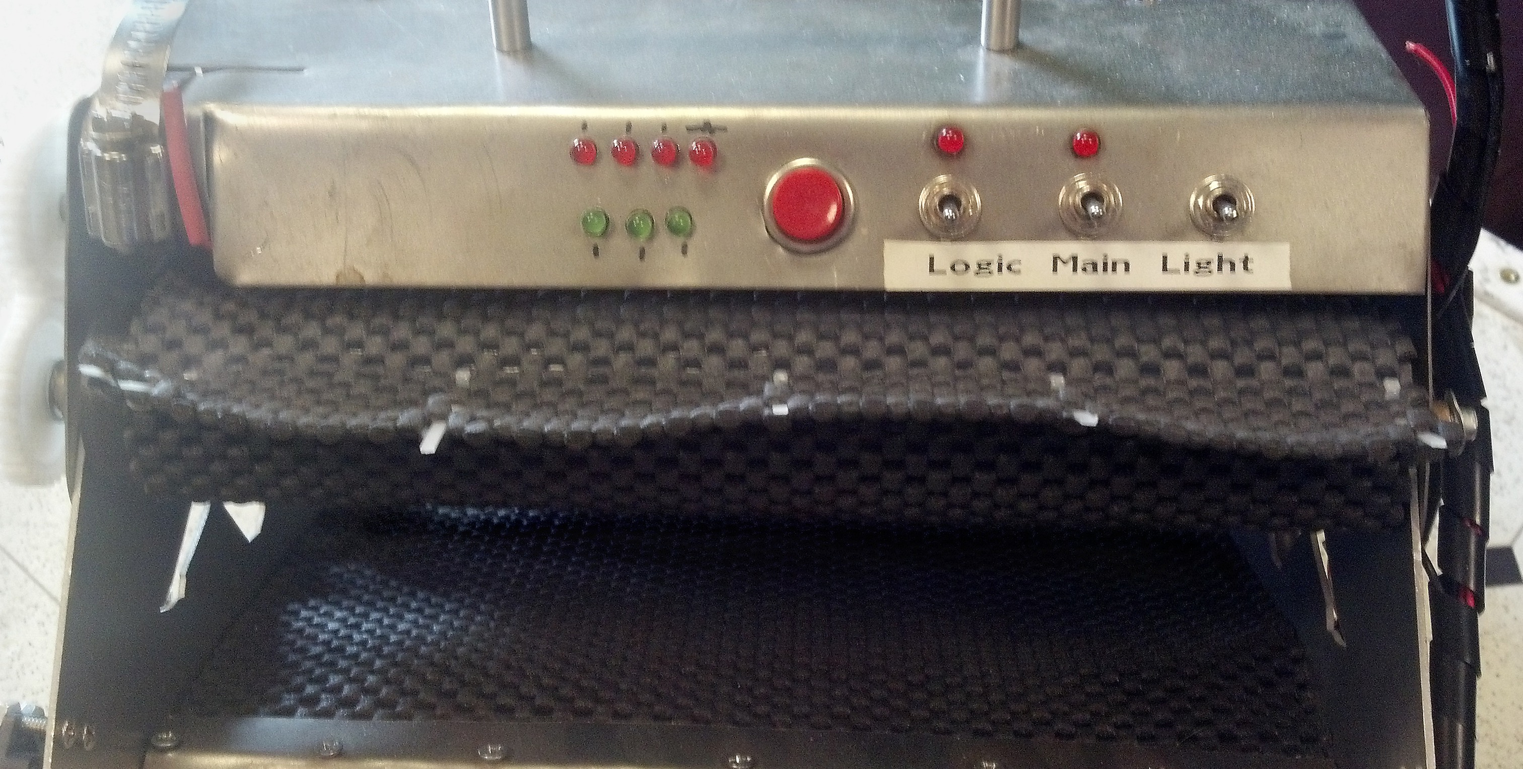
LEDs and switches are mounted on the dashboard on the back of the top of the robot, above the hopper where balls accumulate after being pulled up by the tread.
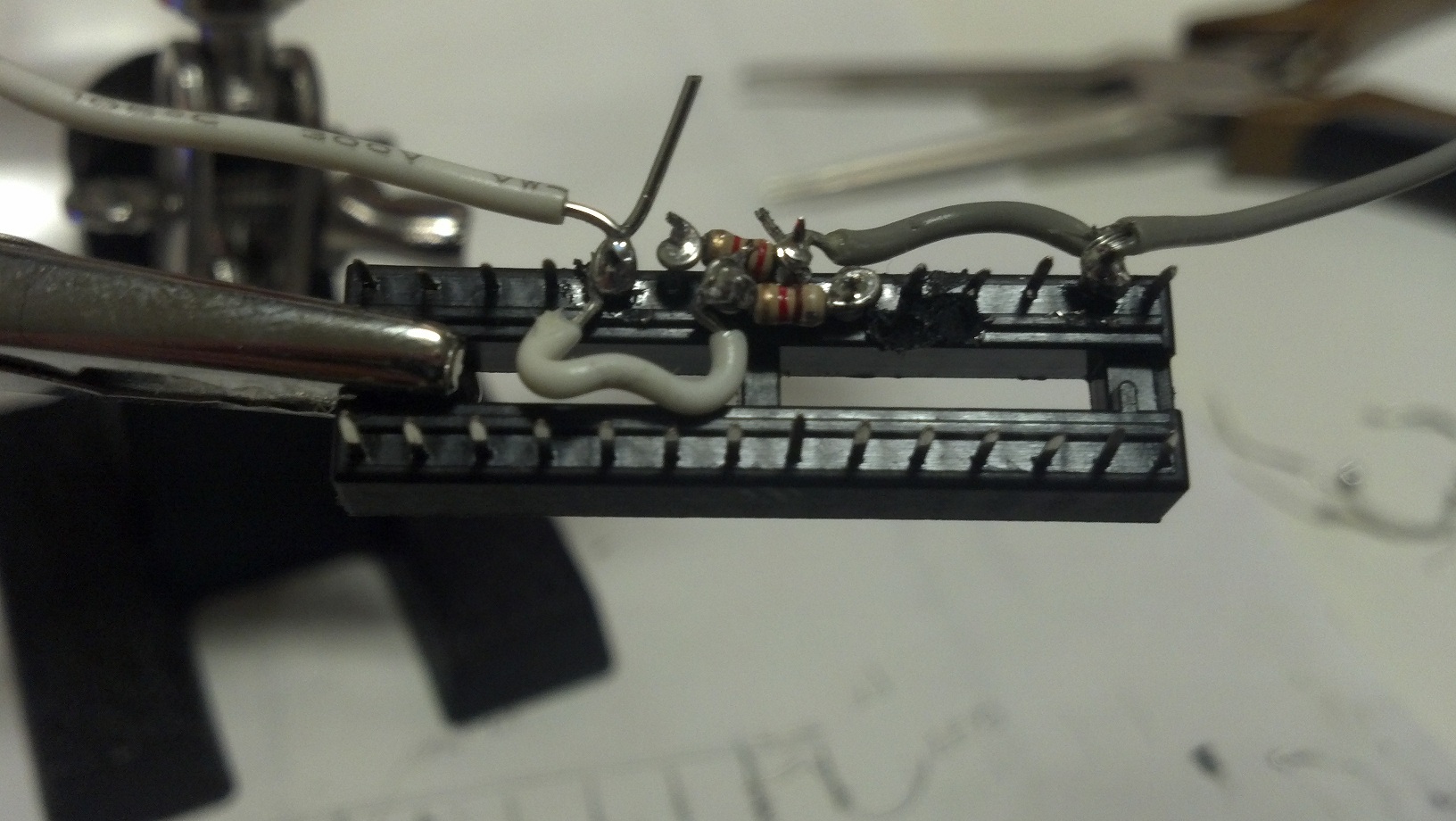
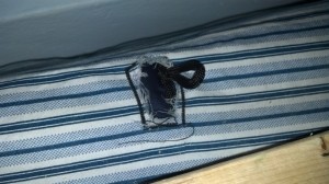
Ball Intake Sensor
Mounted underneath the mesh of the ball intake ramp is a sensor for counting how many balls we pick up from the field, which is useful to know if we don’t want our robot wasting time trying to score until some threshold number of balls is collected. Instead of using a breakbeam or similar single Boolean sensor, we implemented an array of sensors, so we could have an accurate count even if we picked up multiple balls at the same time. Each element of the array is a limit switch read independently by the computer. Because switches are bouncy and noisy, the code lowpasses the signal from each sensor. In addition, the code compensates for one ball tripping two neighboring sensors by interpreting adjacent detections as a single ball detection.
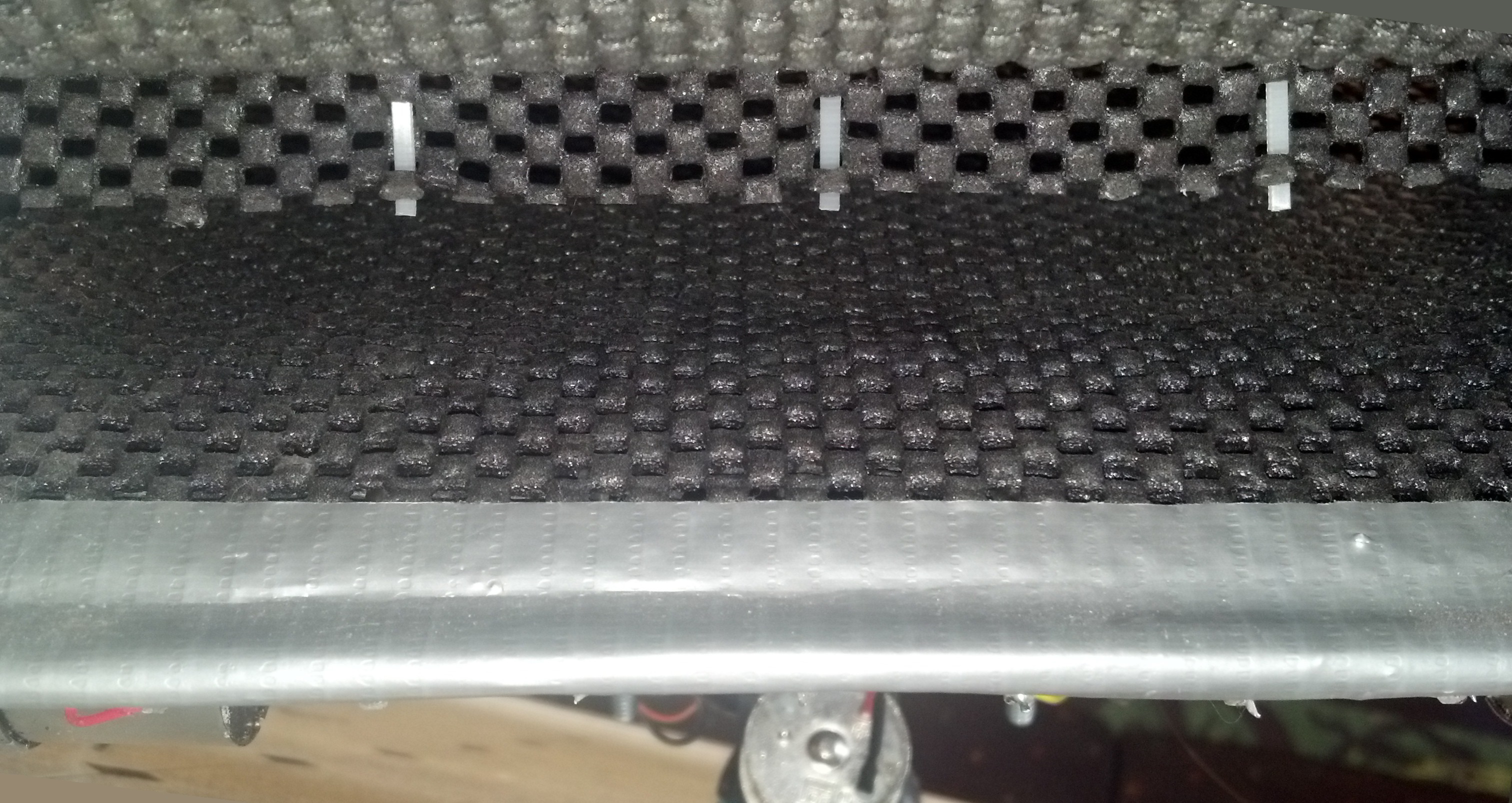
Pictured is the mouth of the tread conveyor; beneath the mesh on the bottom is a line of limit switches, contributing to a slight bulge in the material.
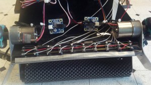
Wiring connects each limit switch on the underside of the ball detector array.
Other Notes
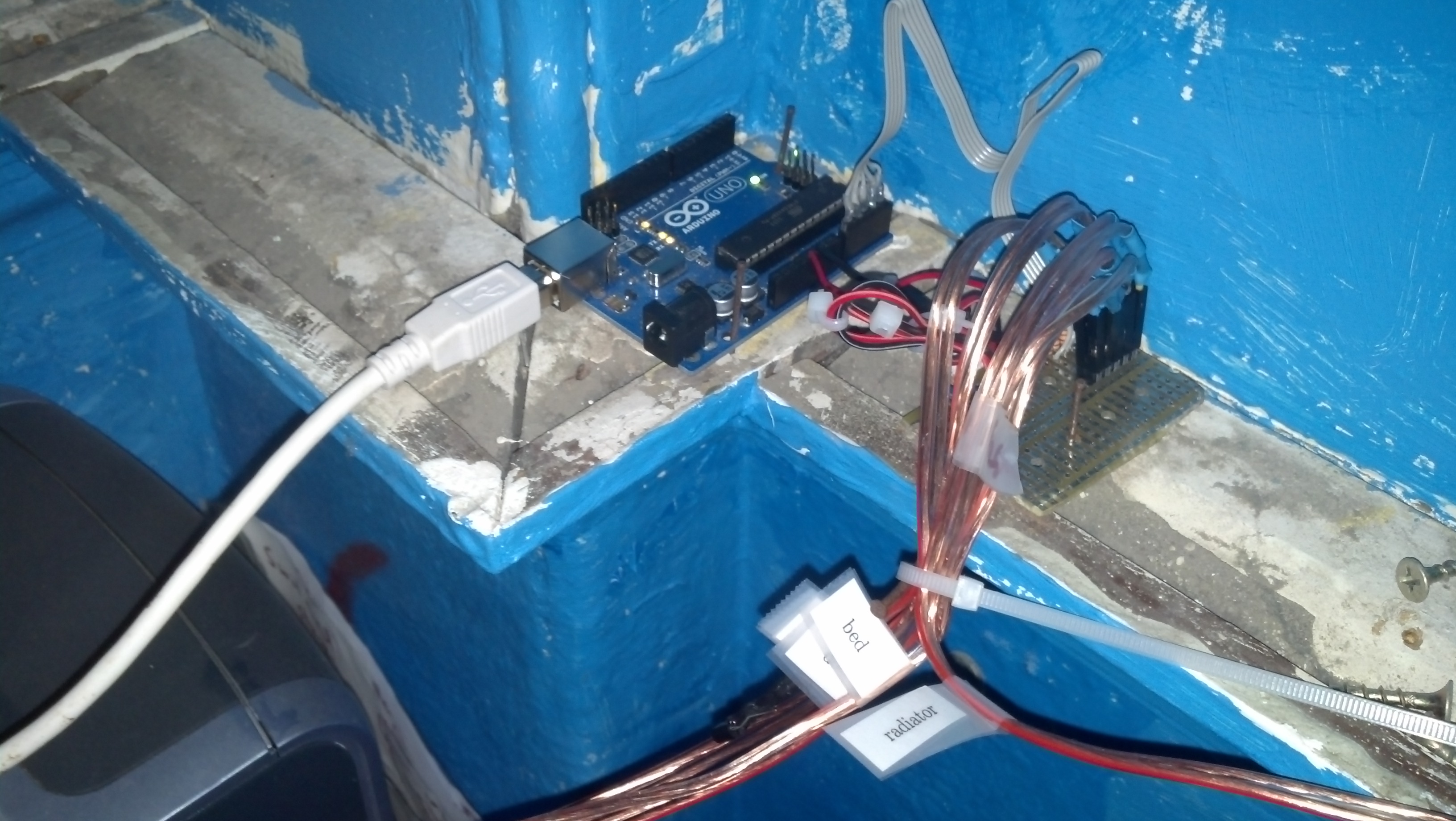
One neat aspect of the MASLab robots was how we set up the processing. The code for our robot ran on an Acer Aspire One laptop, which talked with an Arduino Mega over serial for sensor input. This was a pretty convenient system because it’s easy to implement code on the laptop, and we could implement processor-intensive things like processing the images from our webcam on our laptop.
In the end, we won 3rd place as well as the Two Sigma design award. Thanks Two Sigma!
You can check out the full competition videos on the MASLab 2013 YouTube Playlist, but I’ve pointed out good clips of our robot below with links to relevant starting points in the videos.
- You can see our robot throughout the highlights video–yup, it’s the one that plays nyancat.
- A Good match!
- Another good match!
- One of our best matches! (below)
- We win an award!
You can read more about MASLab at the competition site including how to register. You can also read our team journal for the lulz.