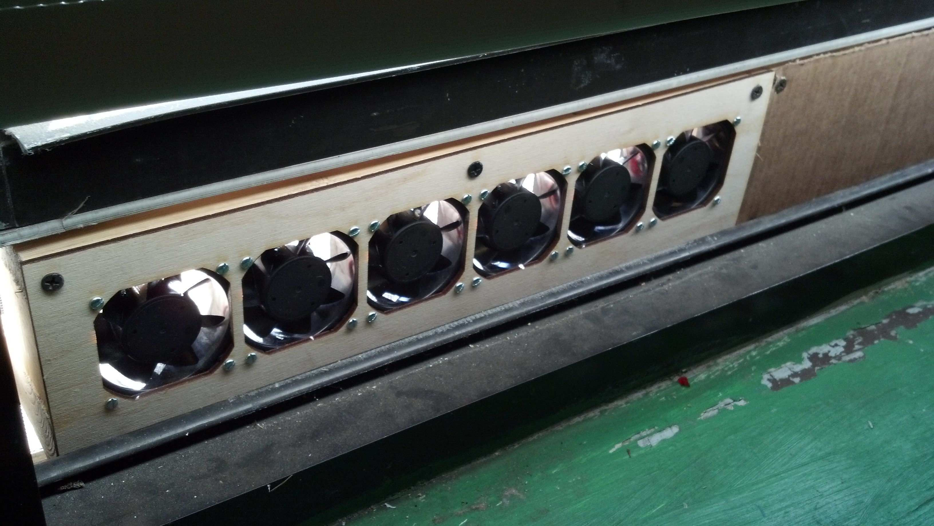
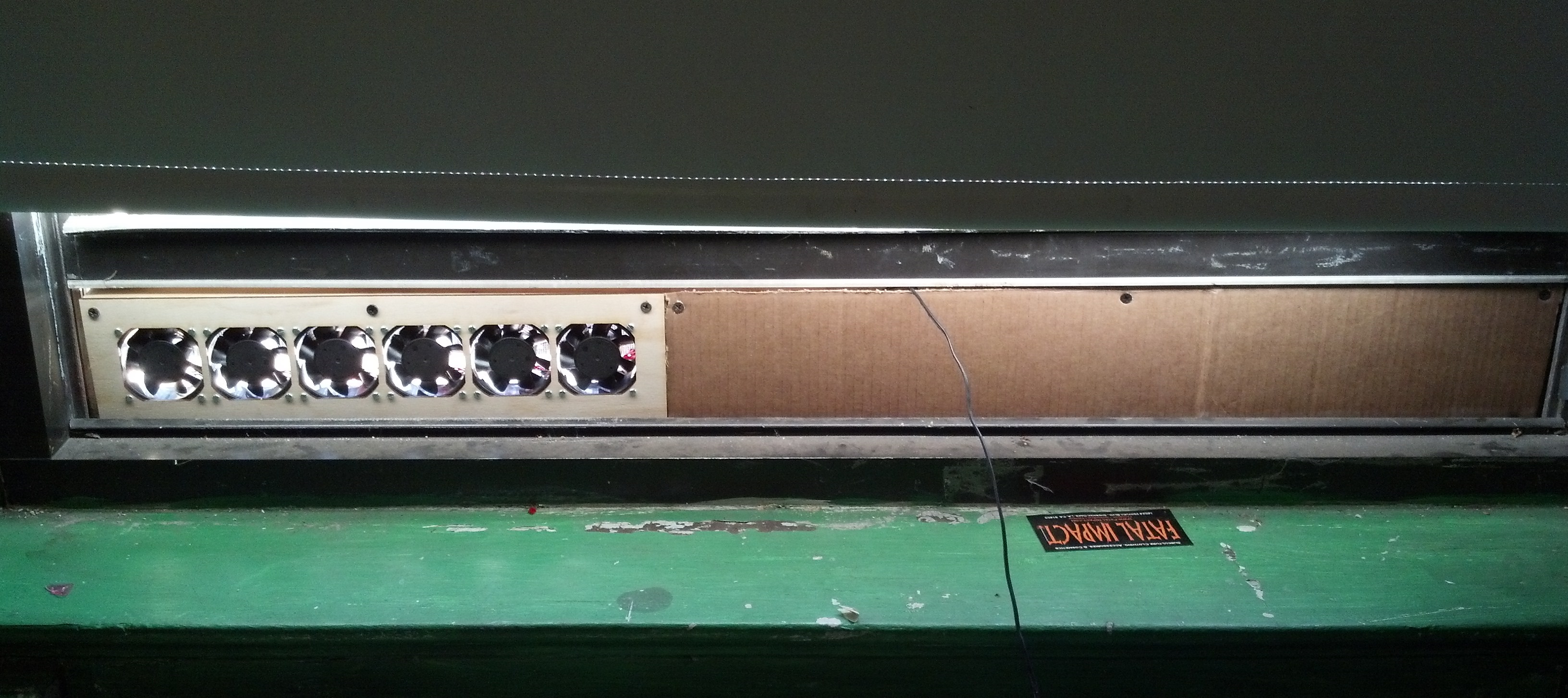
A few days ago I made a low-profile fan for my window out of computer fans. I wanted to mount the fans in a laser-cut frame, so I started by taking measurements and drafting the design in SolidWorks.

This row of fans takes up only a few vertical inches of window real estate.
Often, when I make a design in SolidWorks, I include a file for storing global variables for my project. I liken this to defining global variables or constants at the beginning of a software project. I use this technique frequently to great utility in SolidWorks, but I don’t see very many colleagues use it, so let me elaborate on it.
First, I make a text file called “dimensions.txt” or similar, and, in it, I list all the global variables I’d like to use in my project, like the example below. These include values that I’d like to be the same across parts files. I also include values that I think will have to be changed by the end of the project.
For example, for this project, I thought I might change what computer fan I used and how many I used, so I included mounting dimensions for the fan as well as the quantity of fans.
However, I knew the width of the window wouldn’t change, and was only used in one or two parts, so I didn’t include that constant in my list of project-wide constants.
"dimensions.txt"

1 "depth" = 0.98
2 "side" = 2.36
3 "hole spacing" = 1.97 'horizontal or vertical distance between two holes
4 "fan diameter" = 2.52
5 "fan count" = 6
6
There are some tricks to this text file–for SolidWorks to understand it, all variables must be enclosed in quotes ( ” ” ), comments must be preceded by a single quote ( ‘ ), and the file must end with a newline. Note that in the box above, the numbers on the left mark the lines but are not in the actual text file.
I save dimensions.txt in the root directory of my SolidWorks project. Then, whenever I make a new part, I first use the Equations dialogue in SolidWorks to import this file into the list of parameters for that part; the screenshot below shows the Equations dialogue after importing dimensions.txt. For a parametric modeling software, I think SW sure has this parameter dialogue tucked away, so I have it hotkeyed to Q, the same as the default in Autodesk Inventor, if I recall correctly.
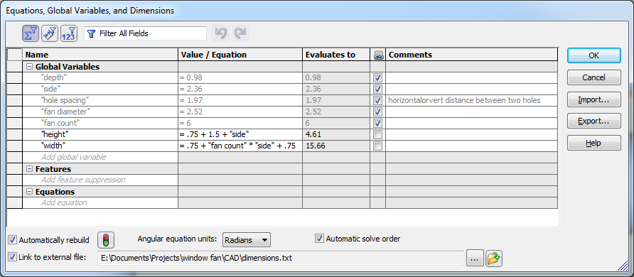
In addition to the globals imported from dimensions.txt, I added a few values specific to this part, the front panel. These values in particular were derived from the globals in dimensions.txt, but they weren’t necessary to be known by every part in the assembly.
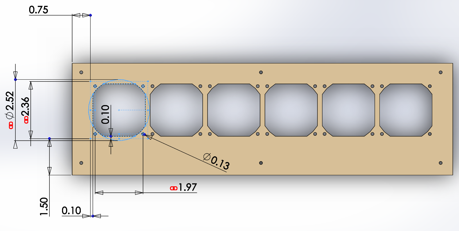
Then, whenever I dimension a sketch or feature in the part, I link those values to the global variables imported in dimensions.txt, as shown below.
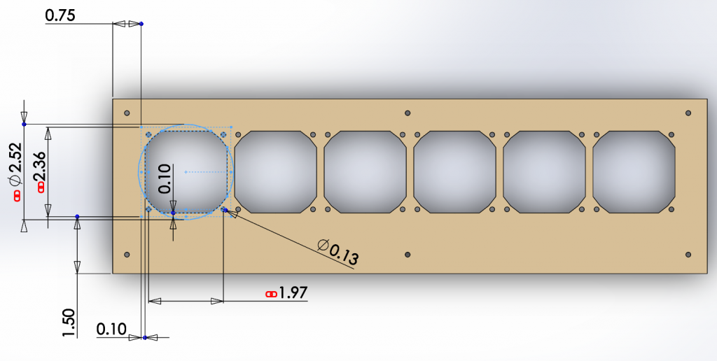
I linked the values of the dimensions here to my global variables, as indicated by the red chainlink symbol.
This allows me to change parameters after I’ve finished the basic CAD. Whenever the part or assembly is rebuilt, SolidWorks automatically refreshes the values in dimensions.txt. Consequently, I can change one value with my text editor, rebuild the top-level assembly in SolidWorks (ctrl+b), and all files update their parameters from dimensions.txt.
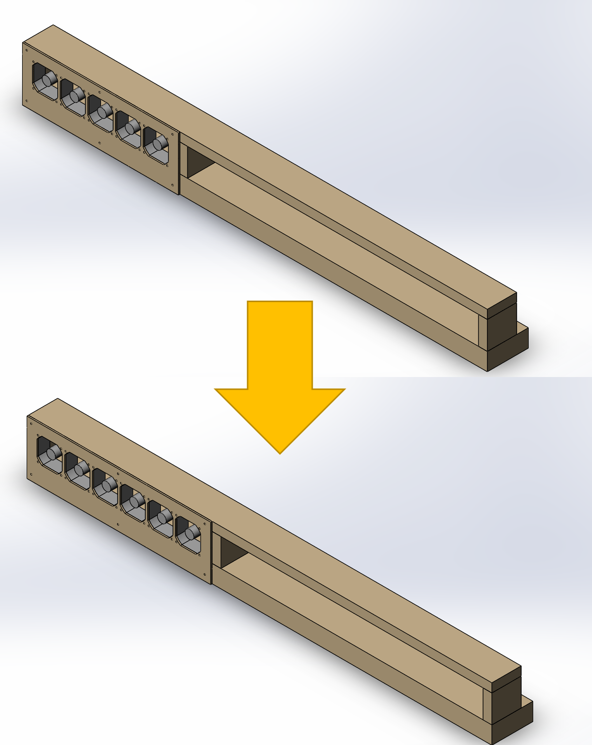
This actually ended up being relevant for this project because I found an extra fan of the same size as my earlier ones, and I wanted to add it to the array. Due to this technique, this change required an order of magnitude fewer operations–my panel and assembly were updated immediately and automatically, as demonstrated below.

Changing from five fans to six required about two clicks instead of a dozen.
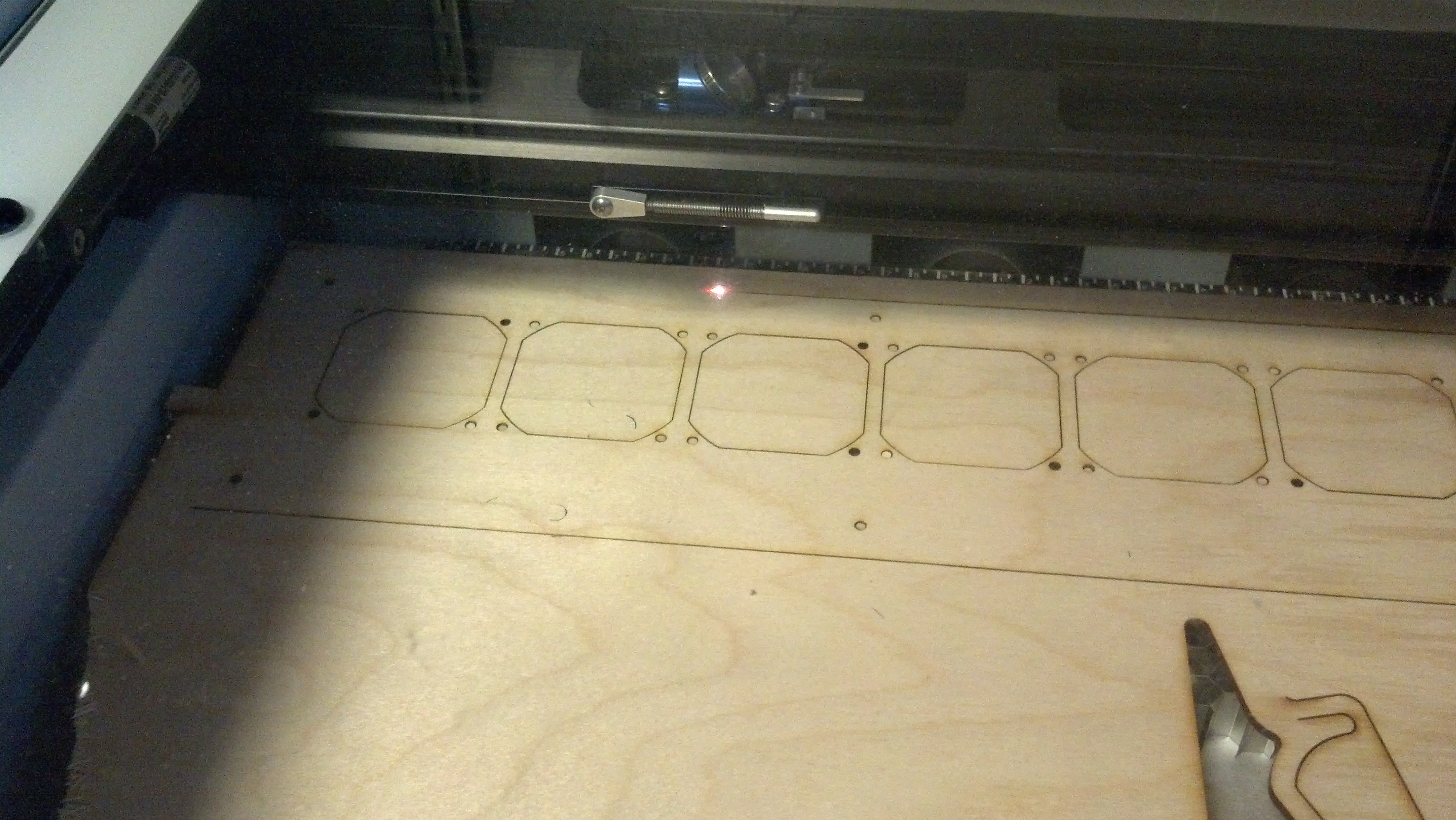
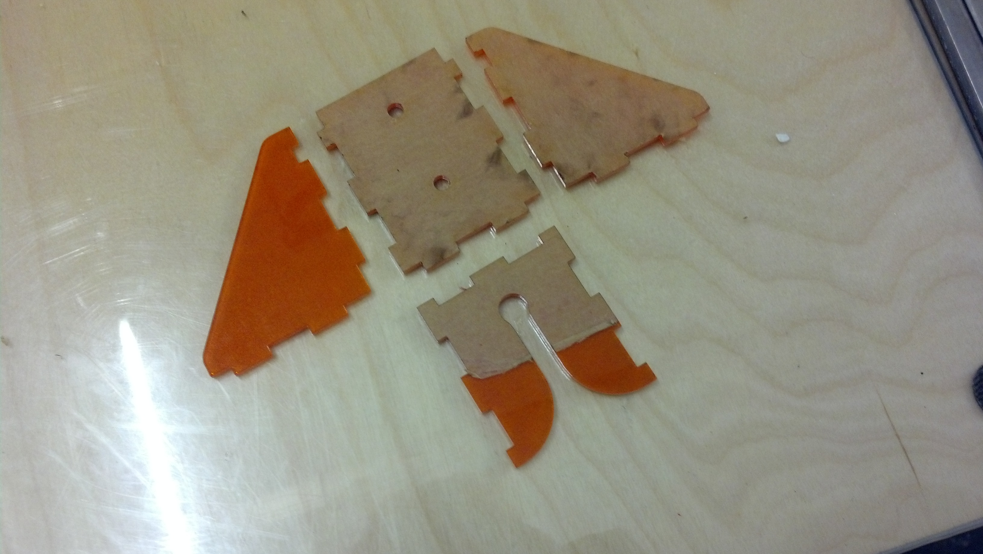
Anyway, after I made this design, I laser cut the front panel.
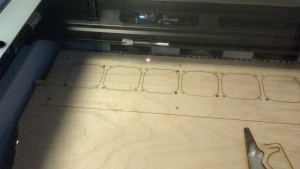
I’m a huge fan of how fast laser cutters are.
Then, I screwed it all together and ran it off of a 5V couple-Amp power supply.
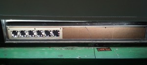
I covered the rest of the fan box with a sheet of cardboard.