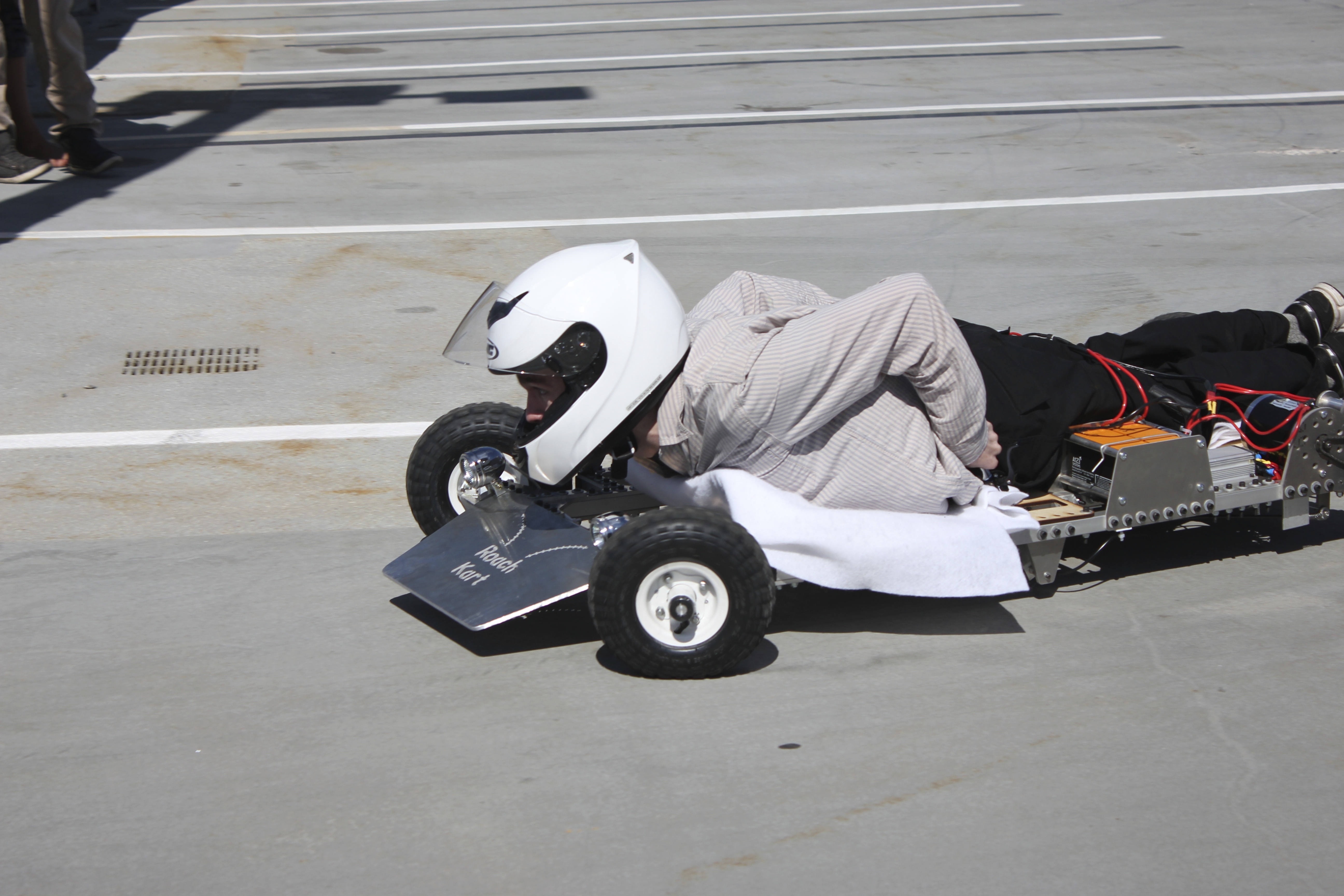
Last semester, I took a class called 2.007, Design and Manufacturing I, which is a project-based class offered by the mechanical engineering department at MIT (course catalog description). Normally, 2.007 students design and build robots for a competition at the end of the class, but this year 2.007 had two special sections: one for building underwater systems and one for building electric vehicles (EVs). I enrolled in the EV section, and over the course of the semester, my teammate Eric and I built an electric go kart, which we named RoachKart. At the end of the semester, we had a series of races. There’s a lot to say about the kart, but for now I’ll just outline our build process.
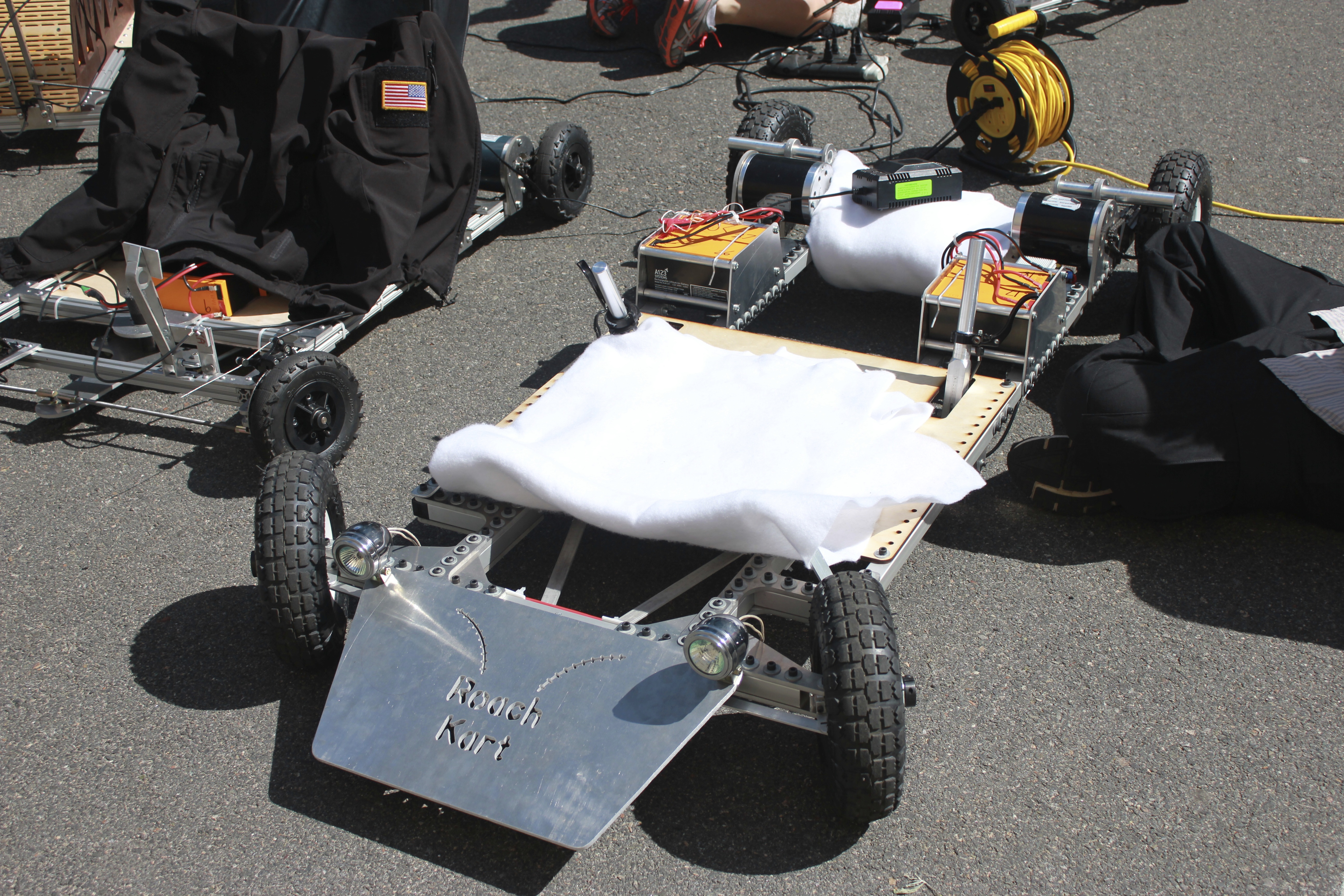
Karts charge prior to the race. Photo by Kirsten L
Our section was taught by EV extraordinaire Charles G, whose relevant blog is here, and who gave presentations on various aspects of vehicle design throughout the semester. At the beginning of the class, he gave constraints for our go karts–20 mph max speed, braking and steering systems, a $500 budget, and more. With this in mind, we set out designing a kart that would satisfy these criteria as well as being fun to drive.
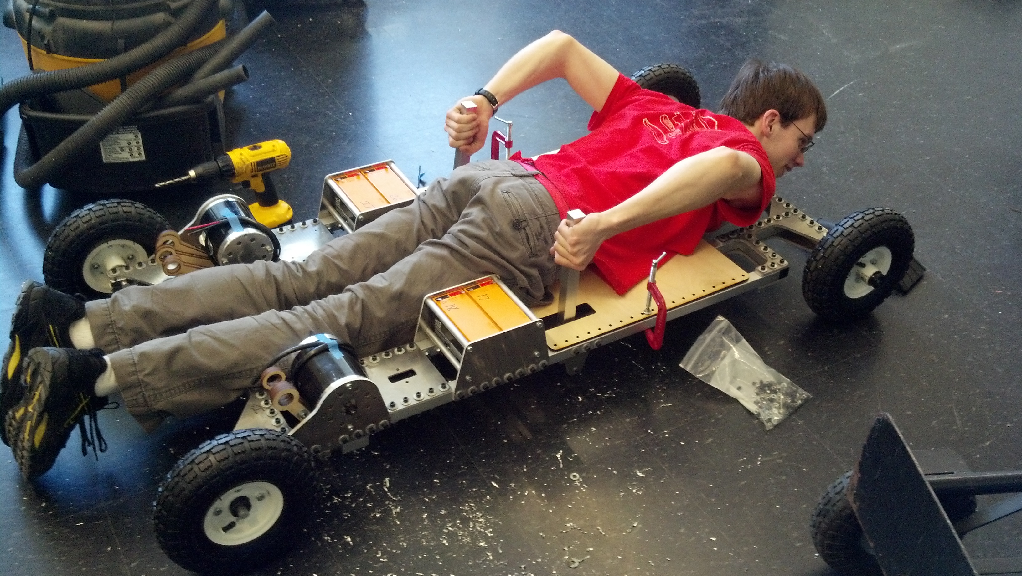
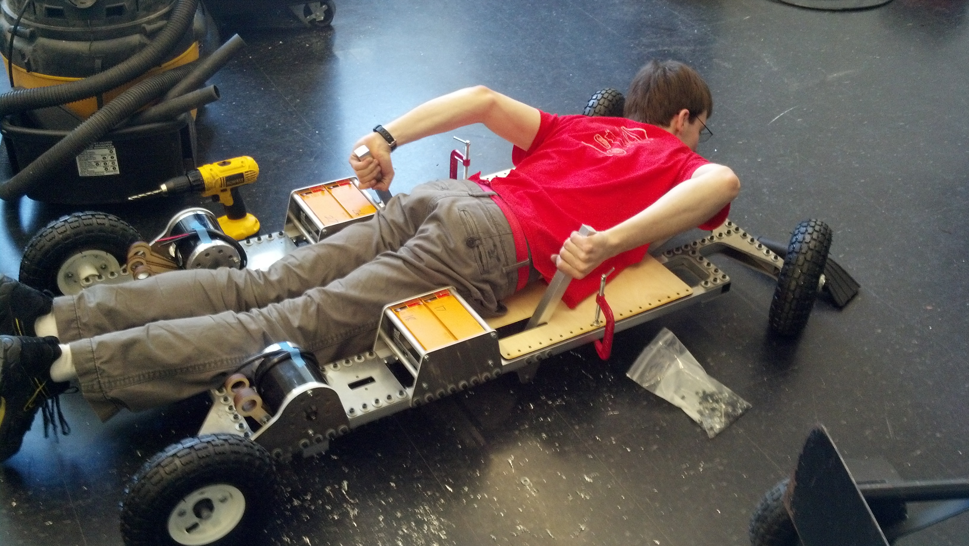
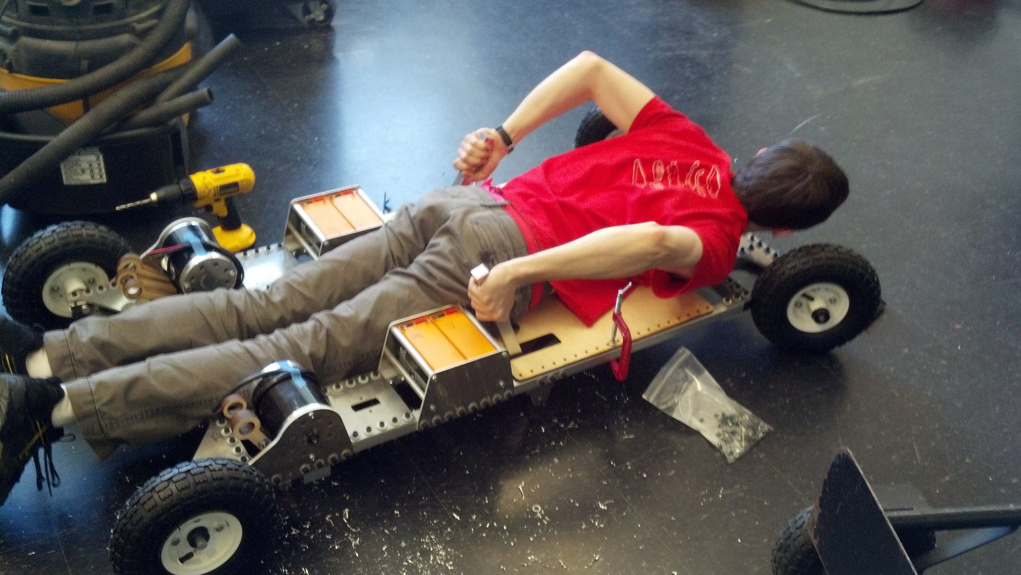
Below, we experimented with various rider positions before settling on a superman-style kart. The rider rests on his stomach with his head facing forward and hands by his sides.
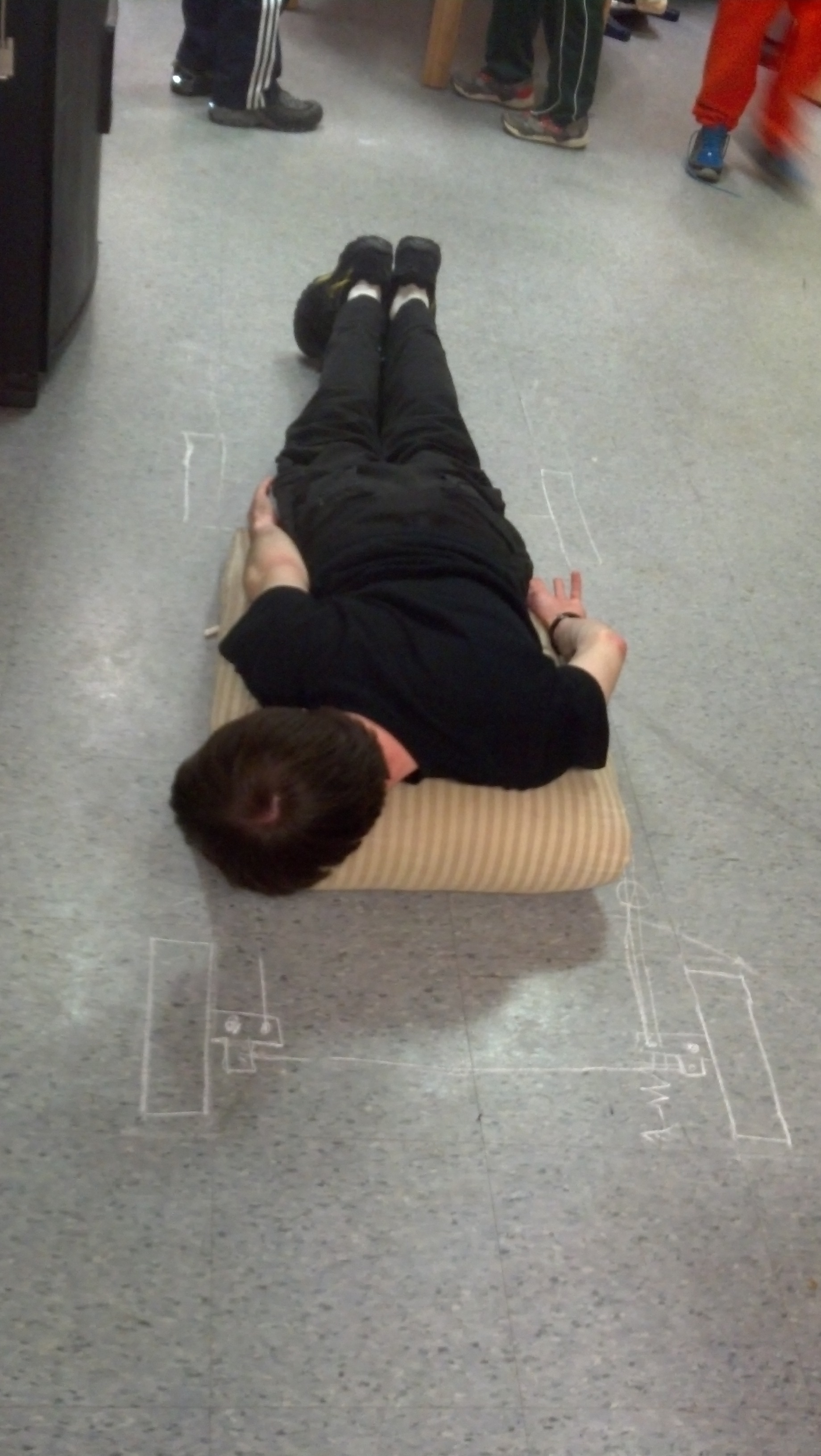
Eric rests on a couch cushion and moves his hands and feet to find comfortable positions for controls.
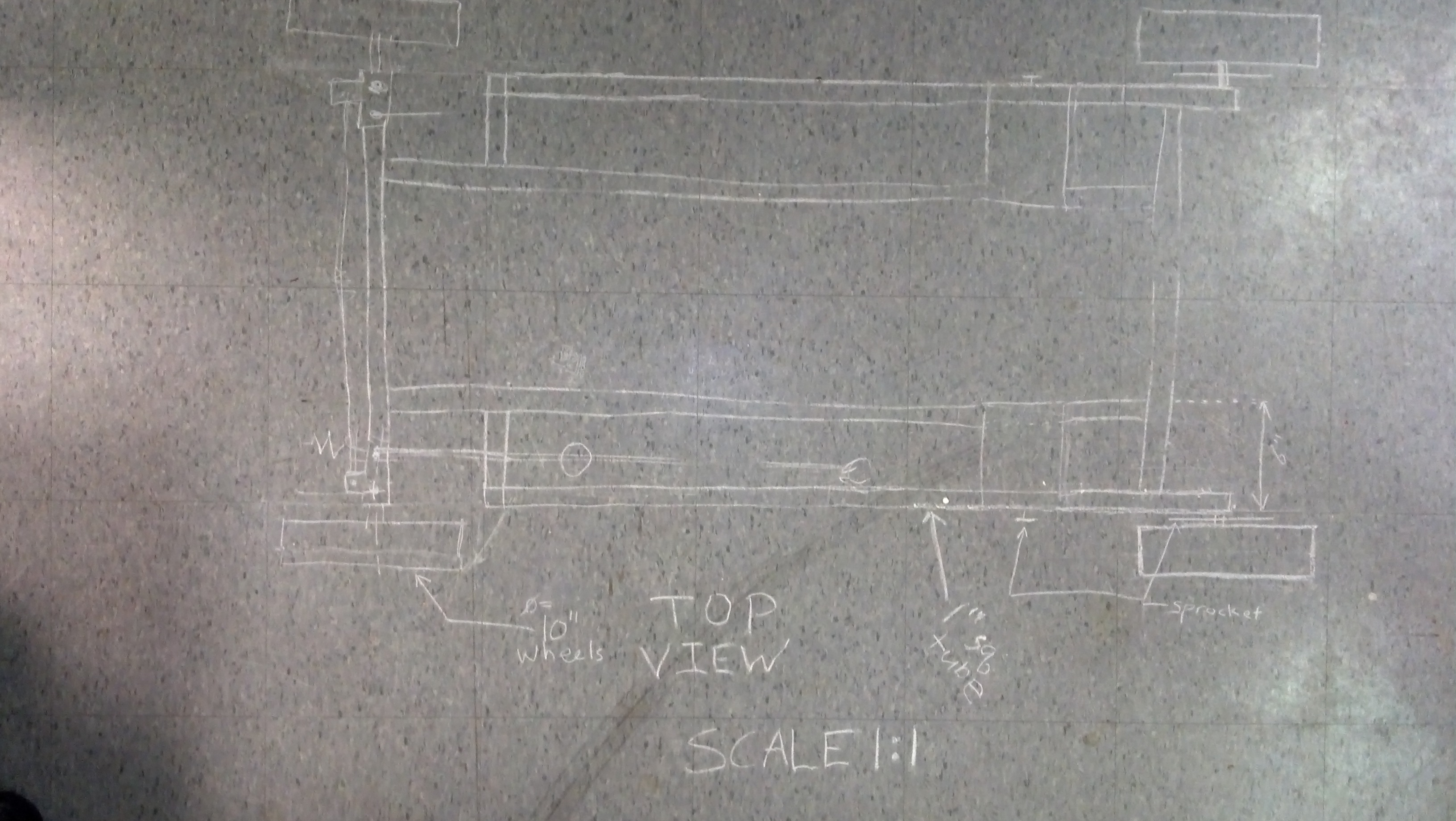
We outlined our design for the kart by drawing on the floor with chalk. Each tile is 1 foot on an edge.
Next, we started designing the go kart in SolidWorks. To collaborate, we set up an SVN repo on which we shared SolidWorks models, pictures, and parts orders. Once we received our first order of parts, we started building the frame. One way we stayed in budget was to use hand-truck wheels from Harbor Freight, which are significantly cheaper than wheels sold on hobby EV sites.
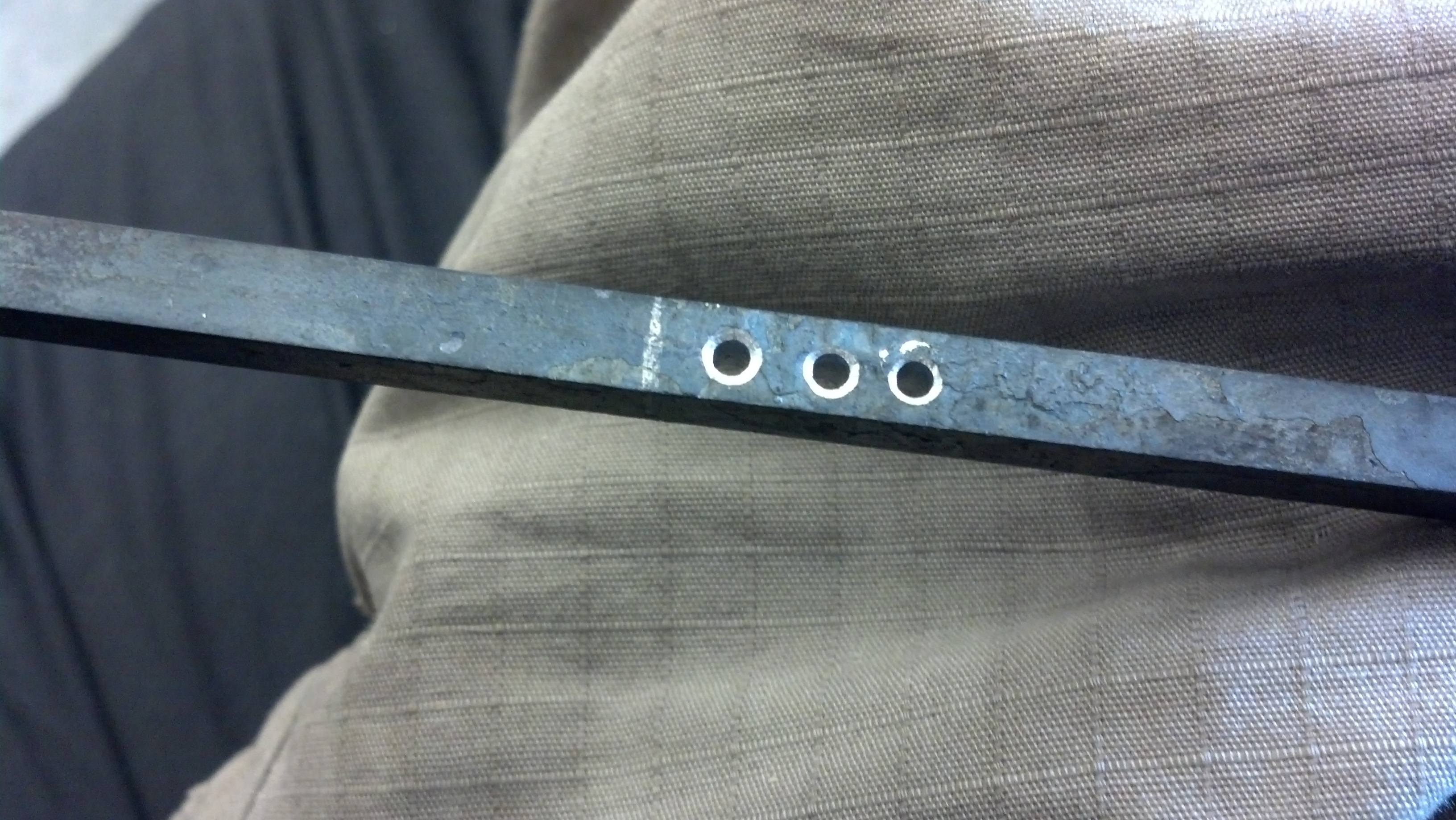
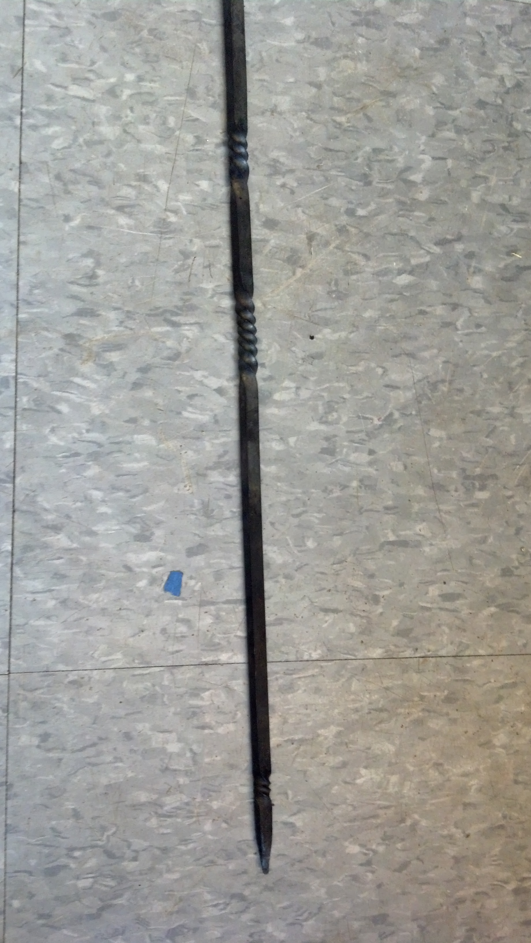
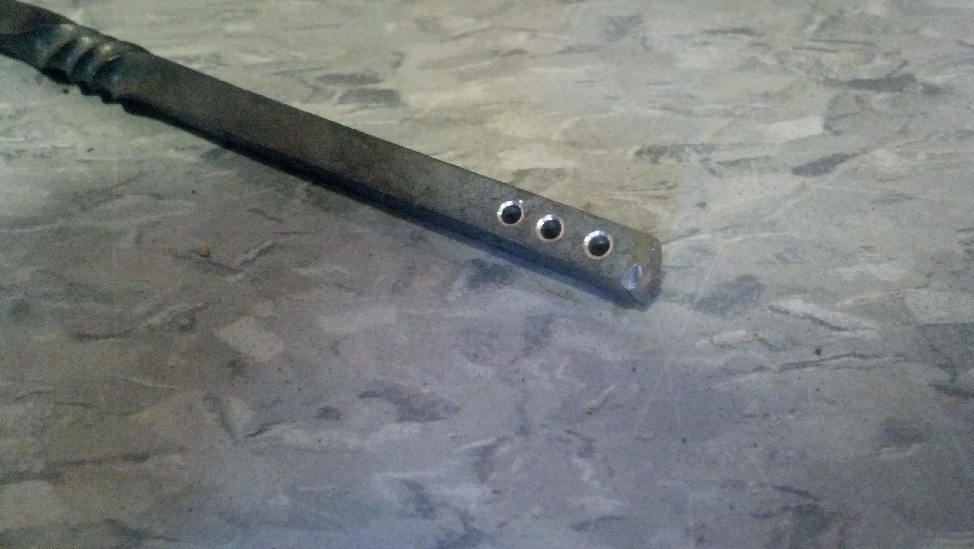
alternatively called ExcessiveScrewHoleKart
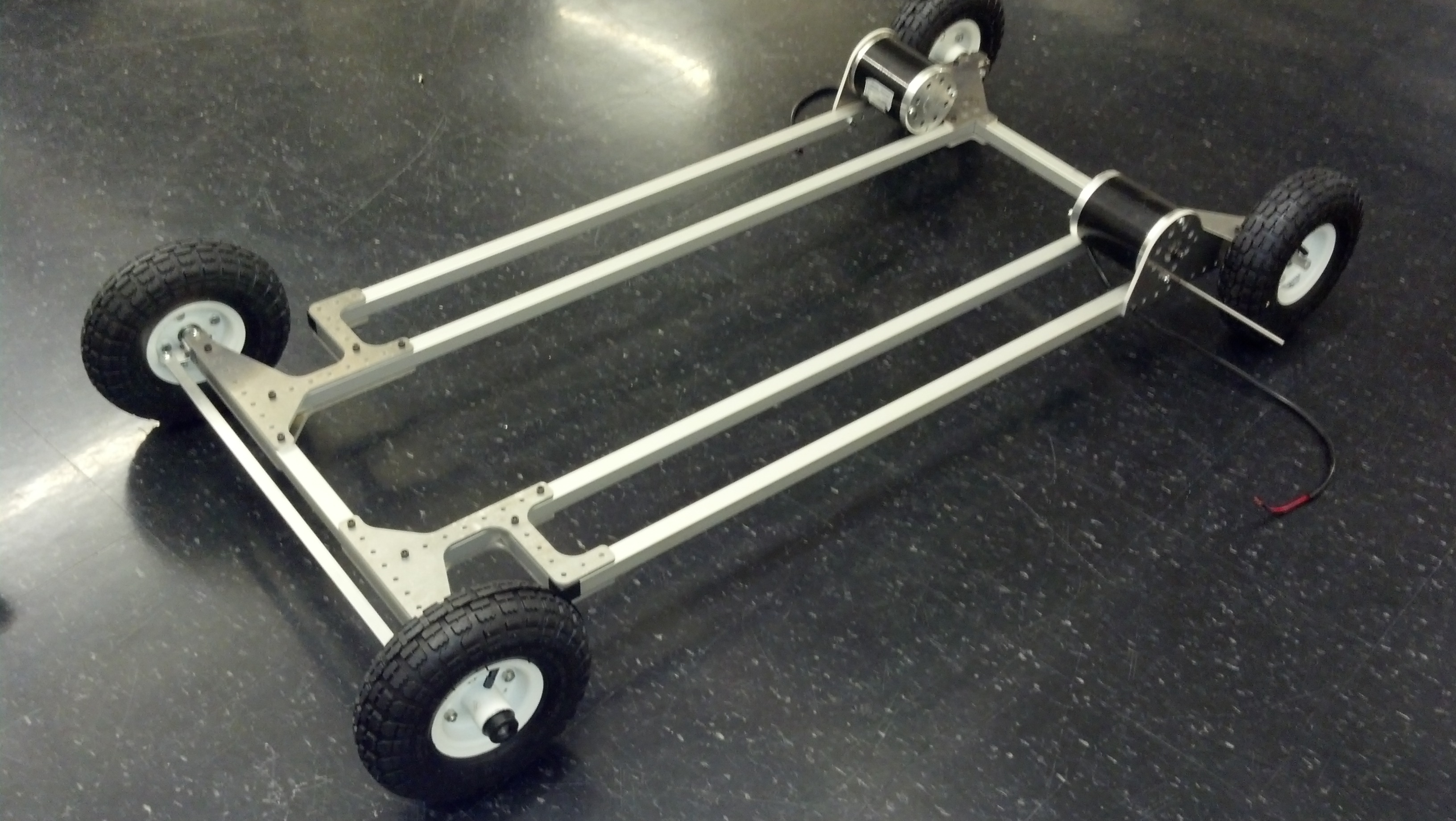
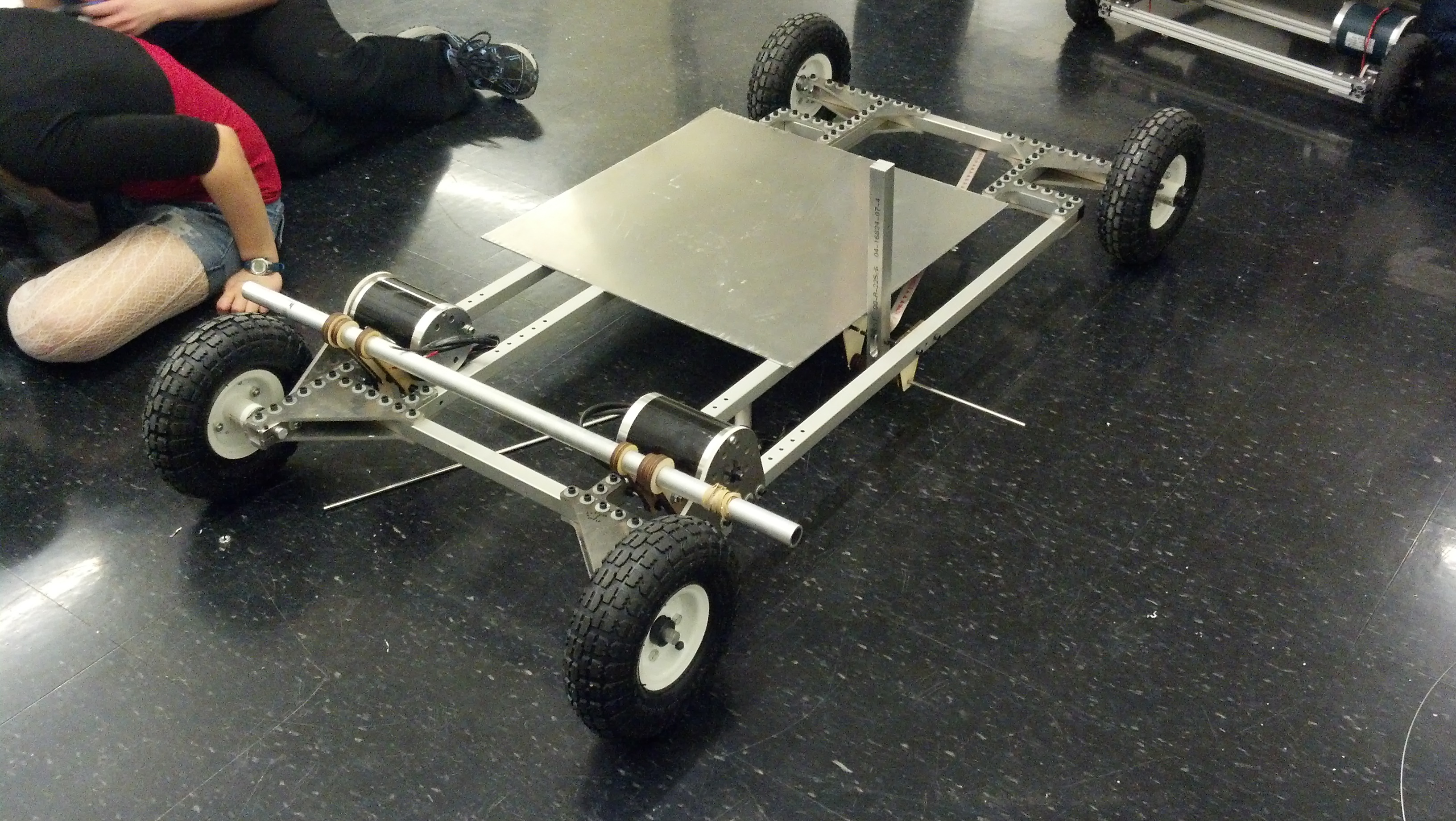
We found a cheap supplier of square aluminum extrusion for the frame and joined the pieces with waterjetted aluminum plates.
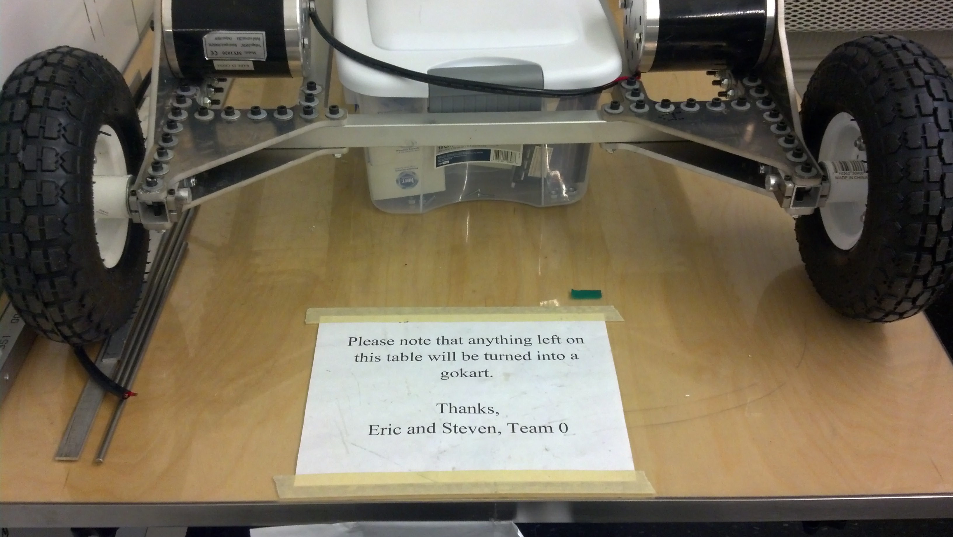
A sign warns fellow students against crowding the workspace with personal belongings.
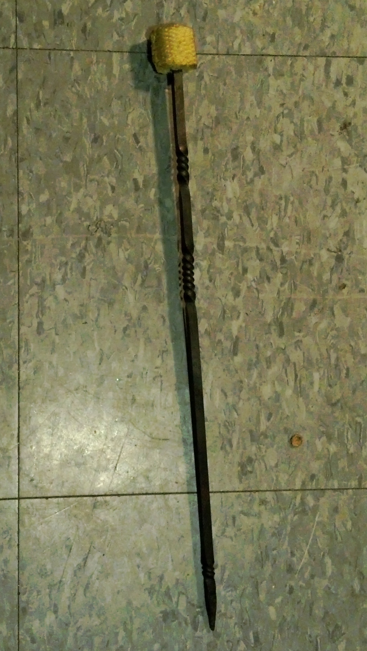
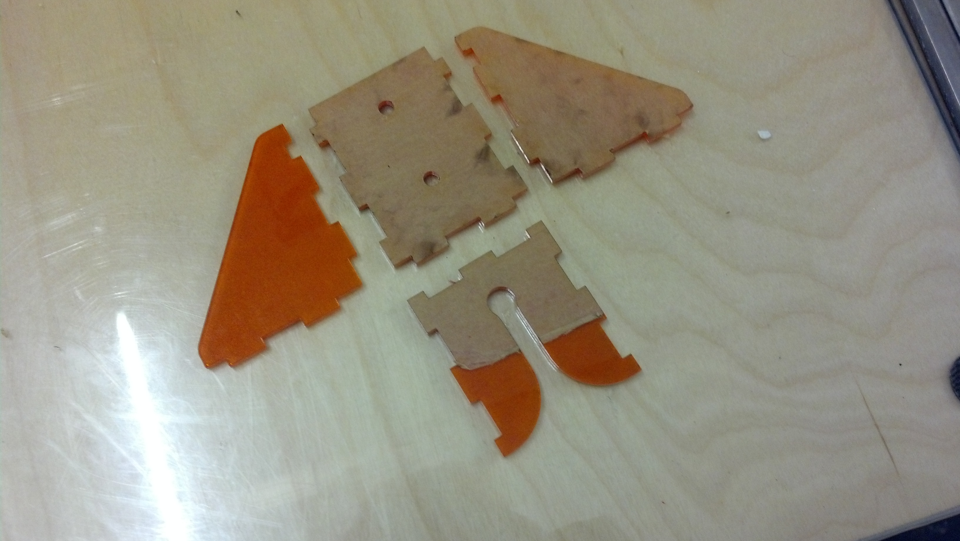
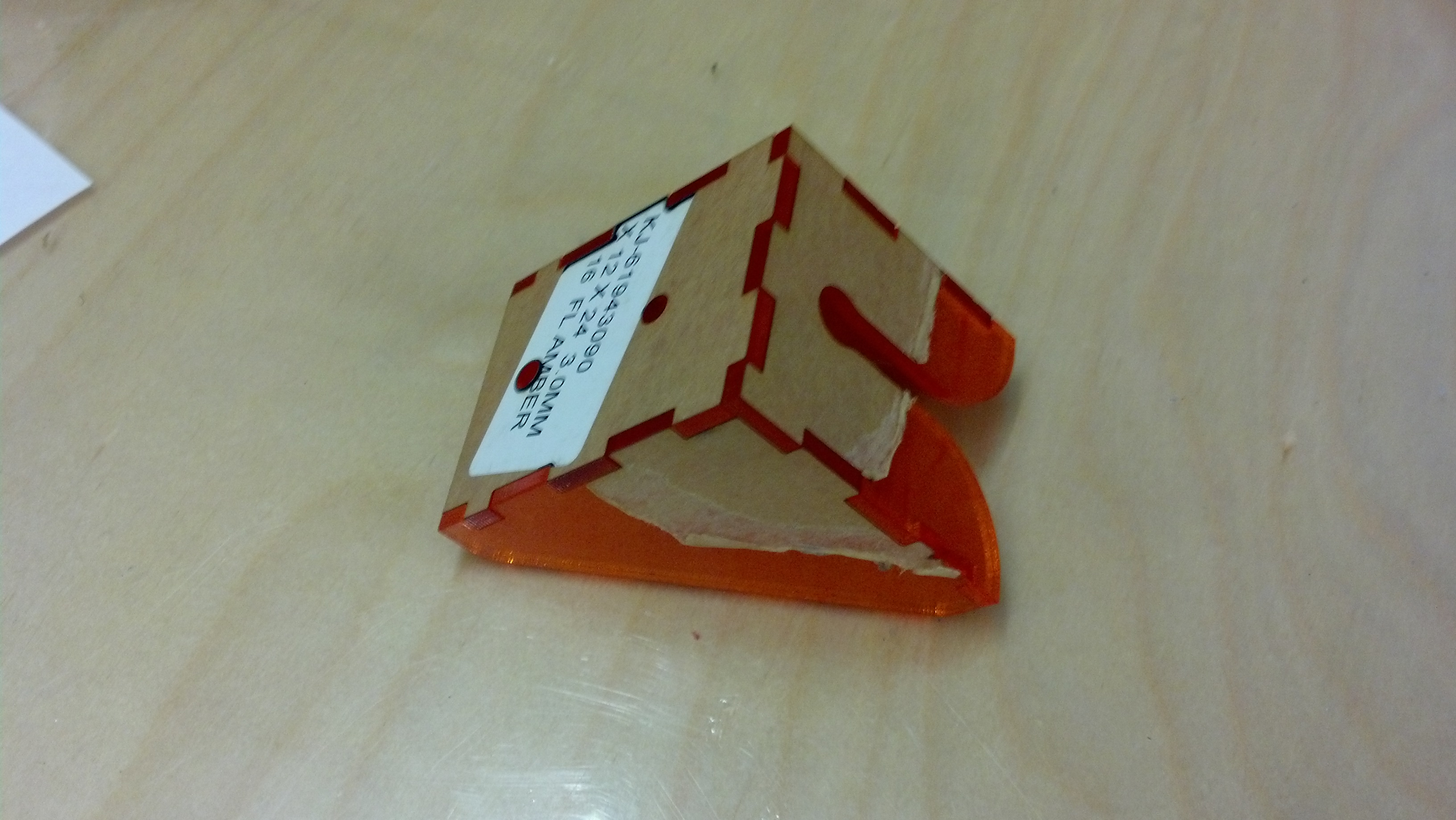
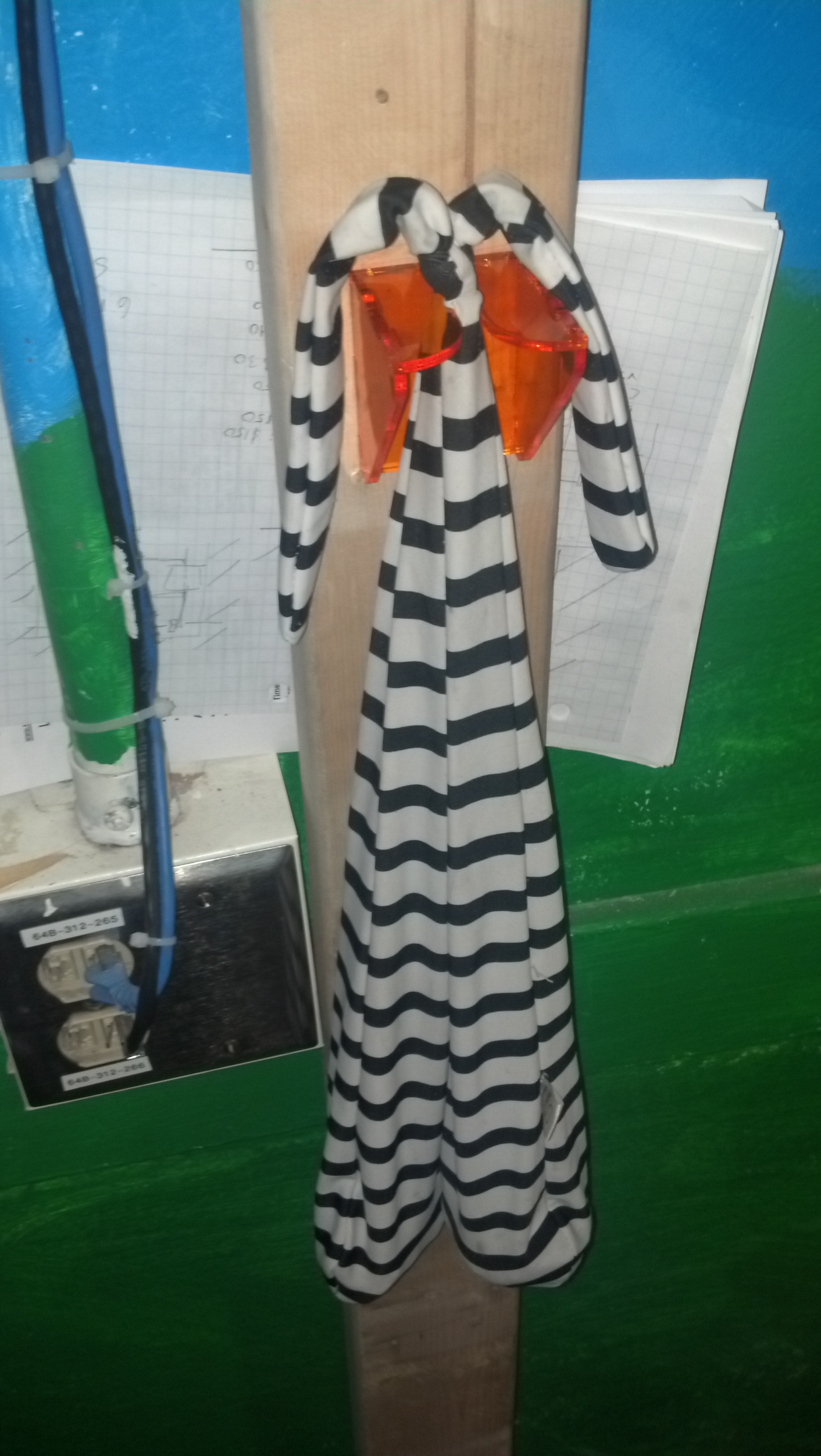
After the frame, we designed more complicated parts like the brakes and steering. Here are prototype versions of them.
Here are prototype versions of steering and brakes.
Finally, we finished the steering and started on other mounting hardware, such as battery mounts, the motor controller, and switches.
 Eric demonstrates using the levers to turn.
At the end of the build, we wired up the electrical system and installed brakes.
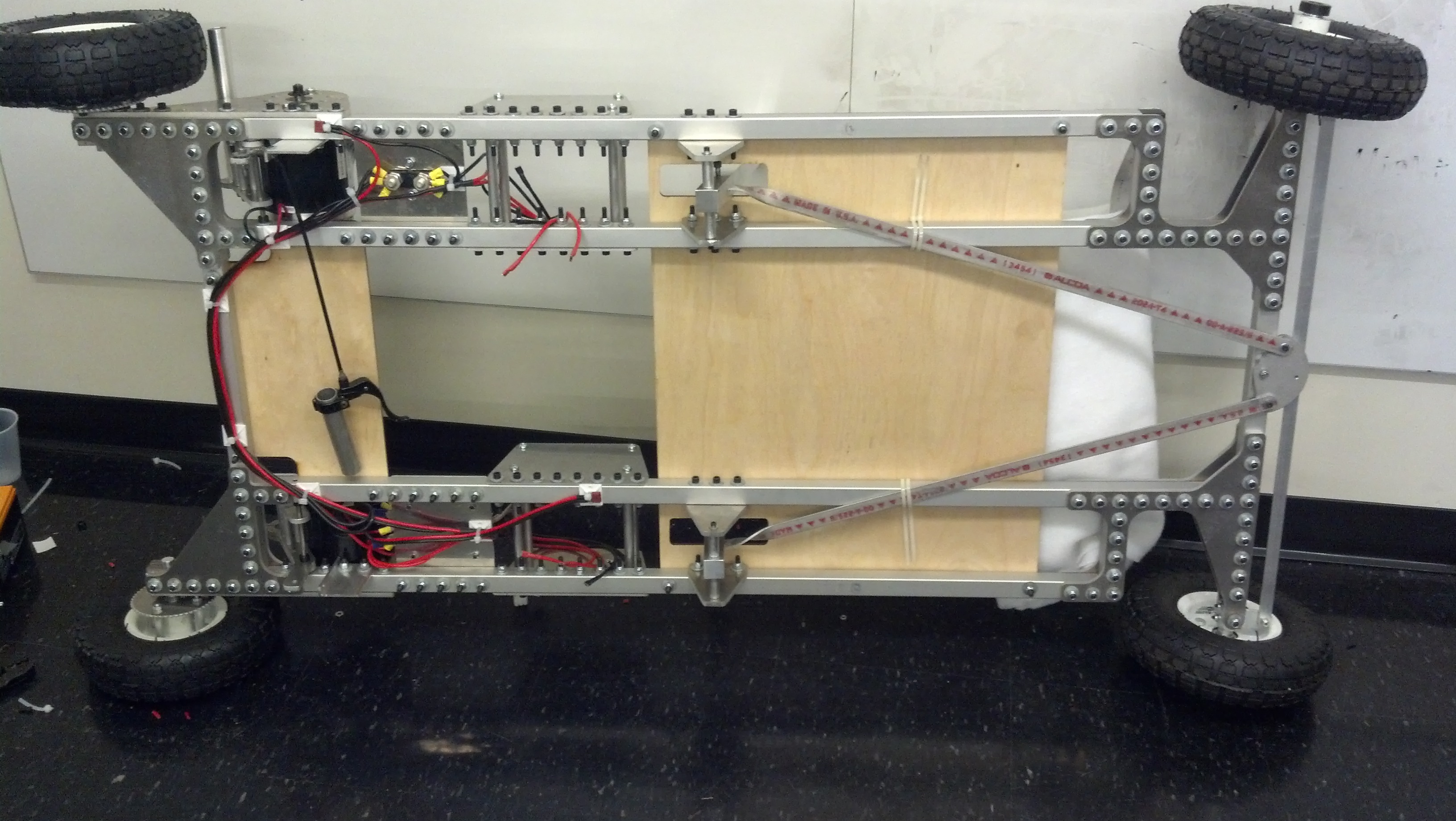
RoachKart is turned on its side to allow access for wiring.
We also added a shoulder rest, white padding for the deck, and a helmet for the rider, all while updating our CAD model to plan what features still needed to be installed.
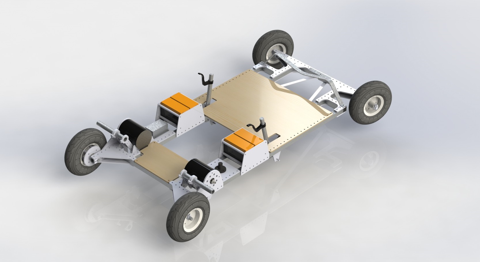
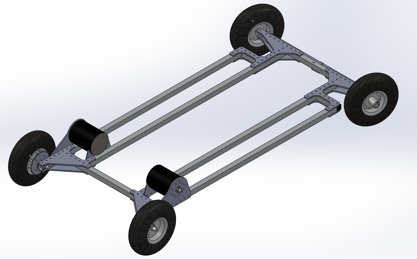
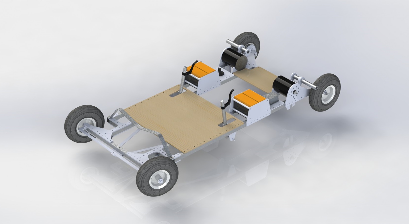 Final CAD rendering shows all major features of the kart except the front cowplow and headlights, which we added on a whim afterward.
Then, we took it for a test ride. Here’s a video of one of the first times we took RoachKart out. Eric and our TA Banks ride it. You can see here why we named it RoachKart–it’s flat and fast. I like how it has low enough clearance to skit underneath a nearby porch. Without a helmet, RoachKart riders can clear 14″ clearances.
Also, driving so low to the ground is really exhilarating.
In the end, our kart performed well, scoring both a low time in the final drag race and a low score in the parking garage hill climb, which measured a composite of speed and vehicle efficiency. At our best, our kart went 50 meters in 7.00 seconds starting from standstill.
The kart climbs to the top of a parking garage and races across the finish line. Photo by Kirsten L
As far as improvements, the biggest thing we would improve if we had time would be the brakes. We implemented scrub-style brakes with a piece of aluminum pressing against the tires, but we suspect disc-style or drum-style brakes would be more effective. In addition, the steering linkages, which were made from 1″x1/8″ aluminum extrusion, could also be improved to bend less in compression. However, for the amount of time we drove the kart, we found that the slop that this contributed to the steering was negligible.
Anyway, there’s lots of go karts that got built, but we think our kart is the most fun to ride.
Edit: Someone asked about the rear assembly, so here’s an exploded view!
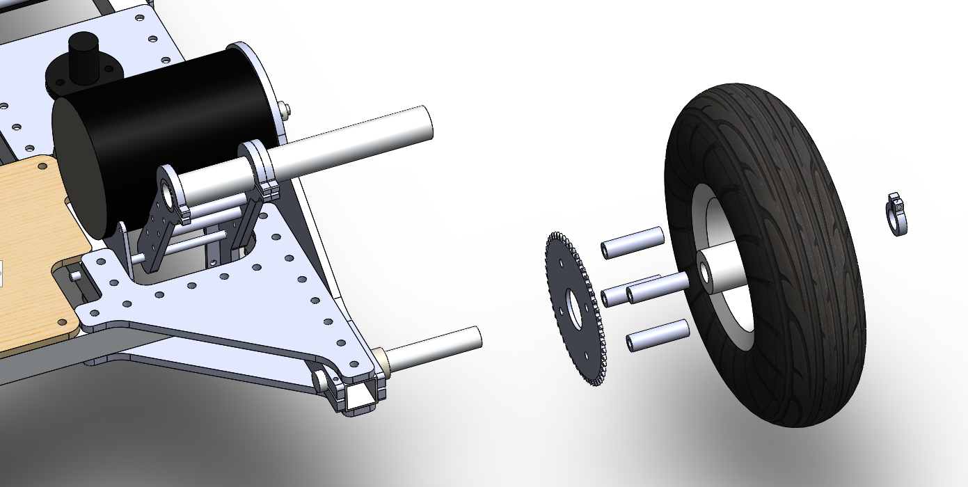
Shown here is the rear assembly including the motor, motor mount, rear axle, a clamp on the frame that fixes the rear axle, and the wheel sprocket assembly. The wheel sprocket assembly is exploded.
For the rear drive, we waterjetted some large sprockets from aluminum and slightly beveled the edges with a sander. Then, we and then bolted them to the side of the wheels we bought from Harbor Freight, standing them off with spacers. The wheels already had bearings in them, so we simply clamped down the rear axles and slid them on. We also added a clamping collar on the outside of each rear axle to keep the wheel assemblies from sliding off. The sprockets on the motors were also waterjetted, and we screwed them into clamping collars and clamped them onto the motor shafts. We then attached chain (not shown) around the sprockets.