Ever wanted to be a robot? Become 0.02% more cyborg with Electronics Facepainting!
Becca G. demonstrates being a cyborg.
I initially had this idea when I heard about a new printer that could print on a variety of materials (c/o Hack a Day). The printer works by printing traces with silver nitrate solution, which precipitates onto the substrate when a second chemical, ascorbic acid, is added. Right off hand, these chemicals struck me as not particularly bad for humans beyond their staining and being mild skin irritants. This gave me the idea to apply them to people. Their risks were minor for the sake of art.
Unfortunately, silver nitrate solution is rather expensive; taking this into account, I searched for an alternative chemical for skin-based circuit traces. The next idea I found was a gallium-based ink, tested in a 2013 research paper I found online by Yu et al. at Tsinghua University. The LEDs on a hand in one of their pictures inspired me, but again gallium was too expensive for my purposes.
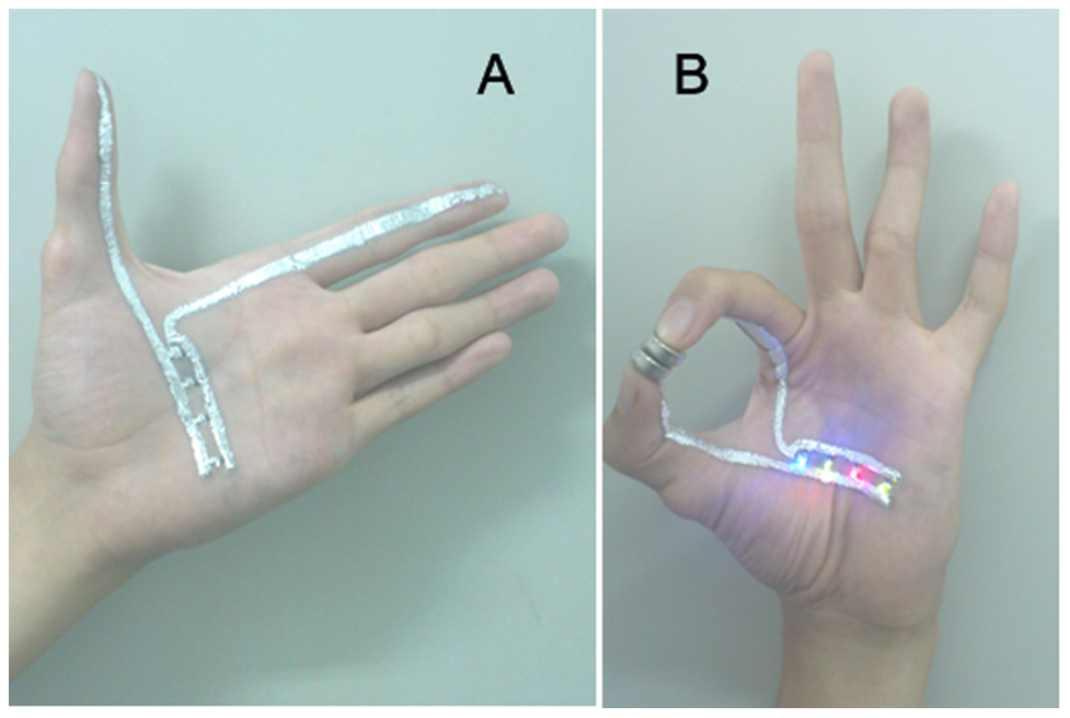
A researcher demonstrates a circuit made with gallium paint, c/o Yu et al.
There are a variety of sources online for how to mix your own conductive paint, conductive rubber, or conductive glue. Most involving mixing the non-conductive version of the substance with graphite powder and produce relatively high resistance products.
However, I settled on Bare Conductive, which makes a non-toxic, reasonably priced conductive ink. Some of their initial videos suggest their product is skin-safe and intended for skin, but they appear to have gone back on this since the Bare Conductive MSDS now recommends against skin contact and any mention of skin is absent from their website. The MSDS warns that it “may cause skin sensitization” due to an allergy to the Diazolidinyl urea in the paint. Maybe they’re also worried about people attaching volts to their skin and zapping themselves.
Anyway, I went with their earlier advice since I had already decided I was fine dealing with mild dermatitis. I ordered a batch for the East Campus Bad Ideas Festival, though I ended up not using it until later. When it arrived, my friend Becca G. and I played around with various techniques before demonstrating it at a party and later MIT Campus Preview Weekend.
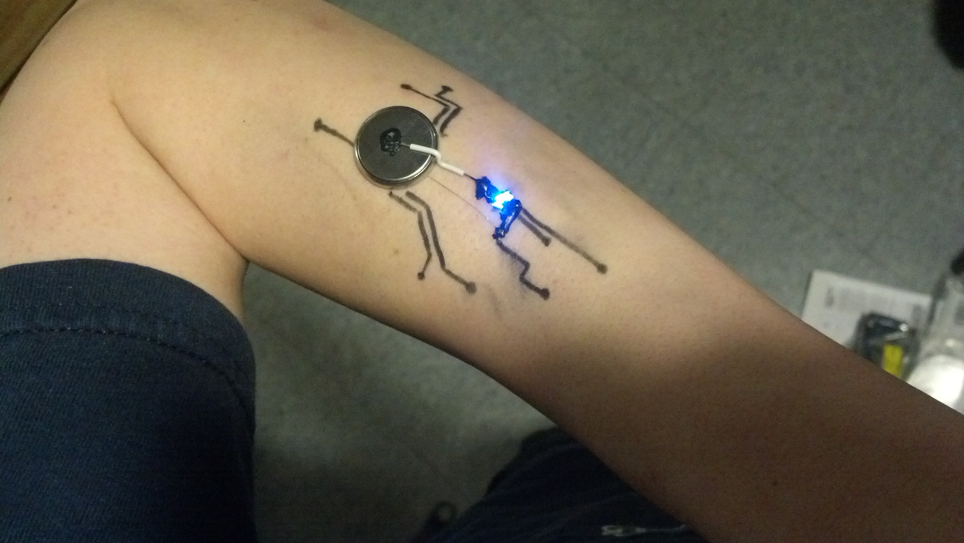
This is the first circuit I painted on my arm. I added details with eyeliner.
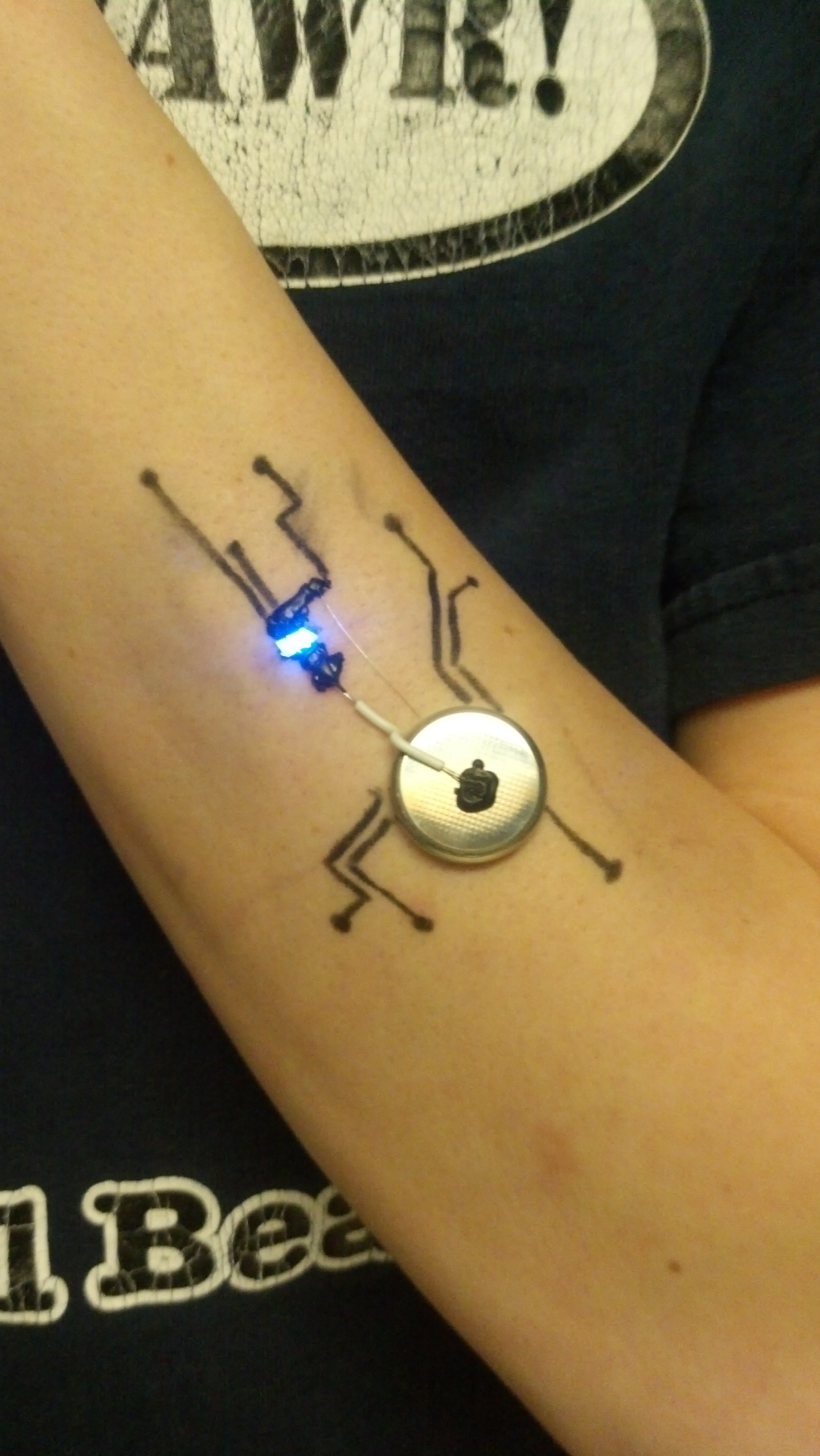
I used Bare Conductive for connections and strands of wire for long traces.
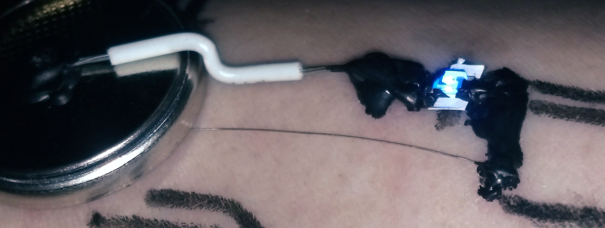
This close up shows the strand of wire as well as the slip of paper I inserted under the LED to make up for my sloppy connection work.
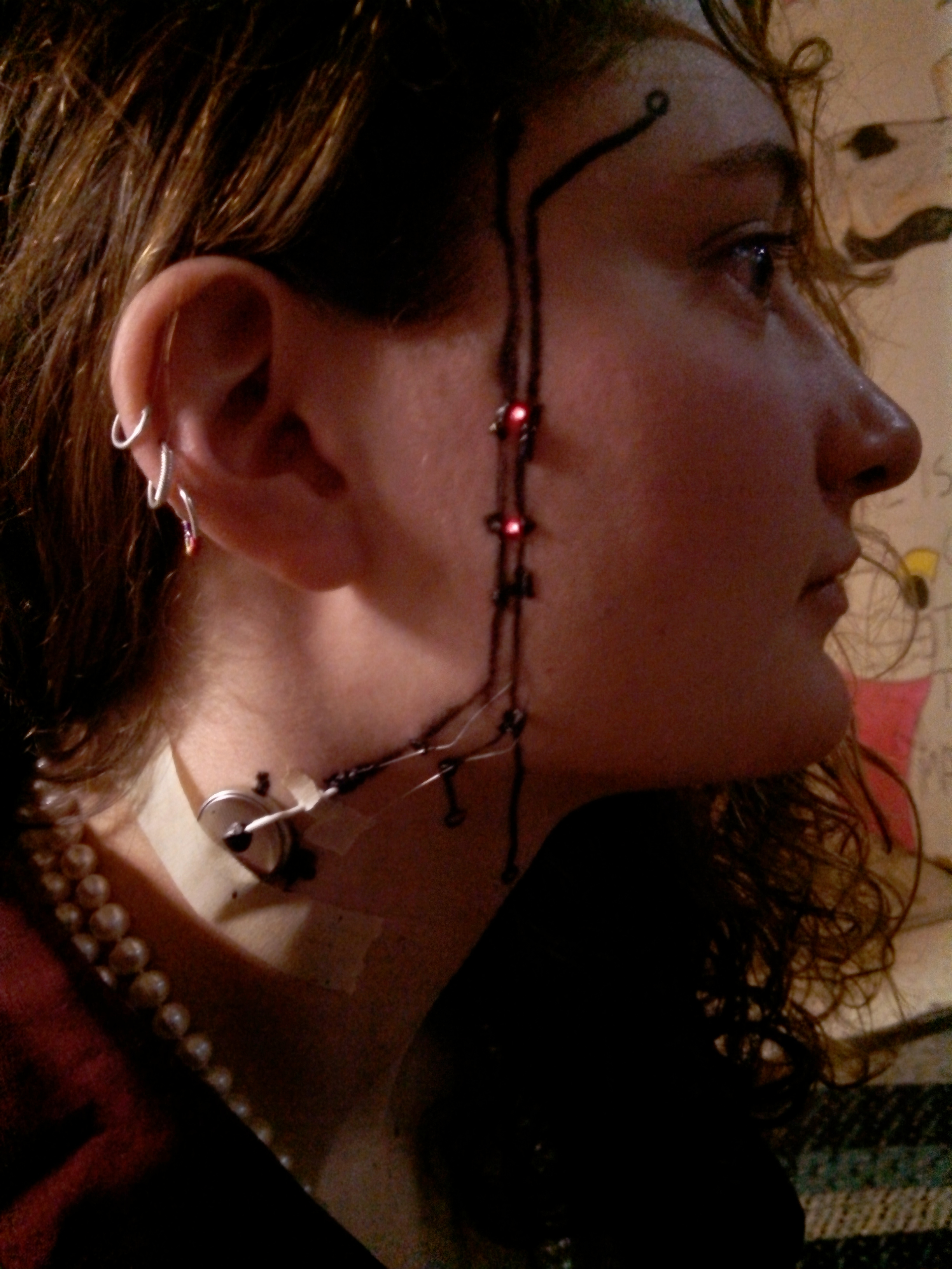
We decorated and annotated the circuits with black, metallic, and neon eye liner pencils. Here are some pics of Becca and me before a party.
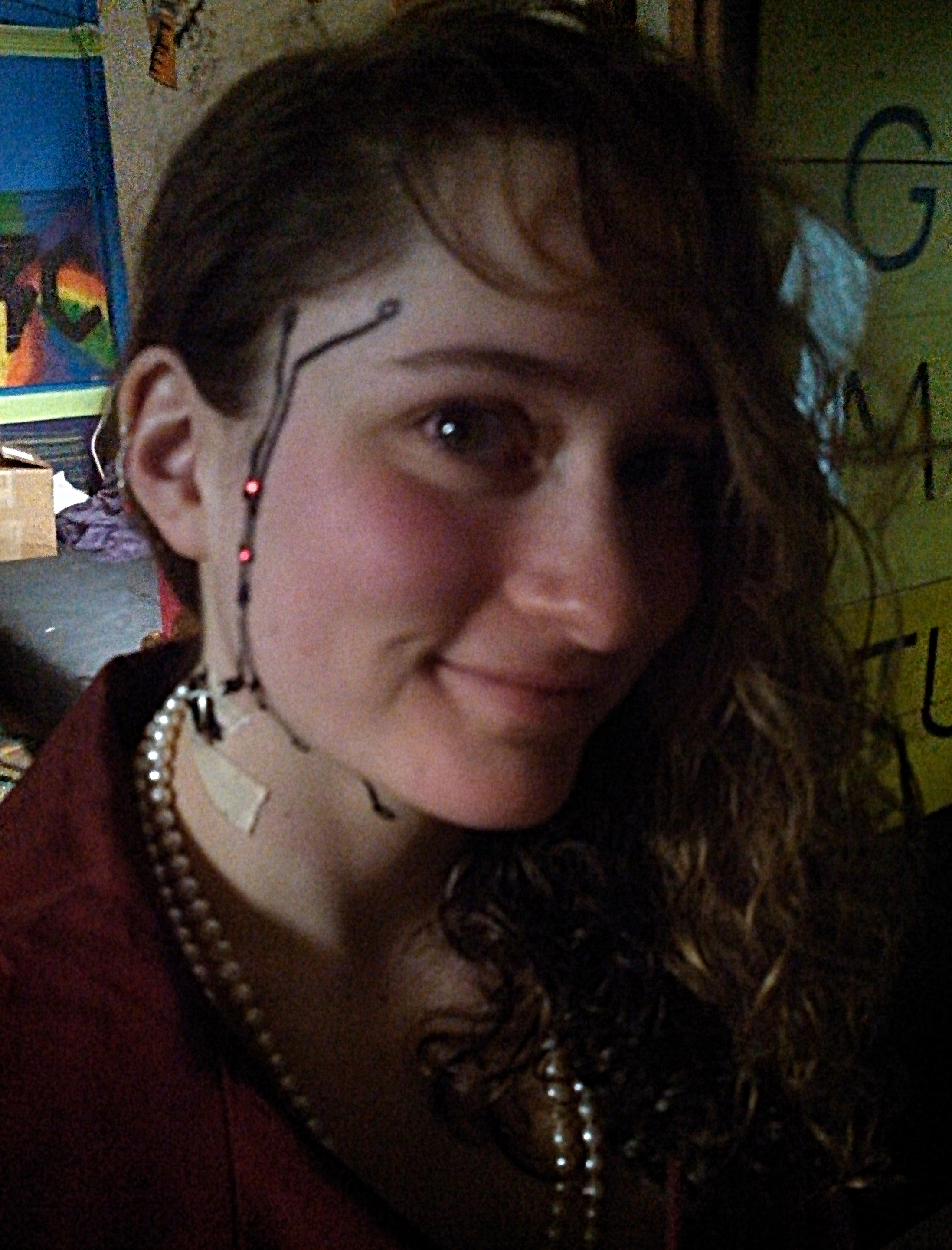
RoboBECCA 9000
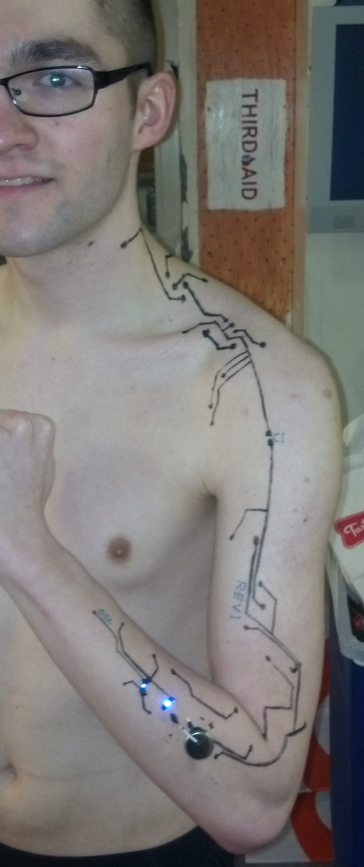
My other arm is robotic.
One thing we noticed immediately was that the conductive ink, while conductive, still had quite a bit of resistance. It turns out the ink is OK for electrical connections and great for making resistors in the 100Ω to 10kΩ range, but pretty bad for making regular traces longer than an inch. As a compromise, I pulled some single strands out of some stranded wire and used these for long traces, securing it with the paint, which I treated like glue or solder.
Mostly, we just painted LED circuits, but I tried a few others. Here’s an oscillator on some paper that didn’t end up working, and I never got a change to debug it further before I cleaned up. That said, I’ve constructed this circuit on a breadboard and artificially added a couple hundred ohms of resistance at every electrical connection to simulate the resistance of the paint at joints, and it worked great, so I suspect this circuit could be successful with some tweaking.
Works on paper (top right corner), but doesn’t work on this paper
One problem I had was the fragility of the circuits–it was important to avoid accidentally brushing your skin against any rough surfaces. In the future, I’d like to try using clear liquid latex to secure some of these circuits.
If there’s interest in this, I can post some step-by-steps on how to make your own Electronics Facepainting.