Archives

All posts for the month December, 2012

Last IAP, I ran into a problem. I have lots of kinds of audio signal sources: my laptop, my desktop, and mp3 players are the major ones, and each produces a separate mix of sounds. However, my preferred destination for all these sources is my pumpin’ Klipsh desktop speakers. I wanted a way to mix all these sources through software without having to acquire or build a lot of new hardware.

My solution was to use the sound card of my desktop, which has ports for line out, mic in, and line in. My speakers are connected to the line out port, and I have a 10′ trs cable running from the line in to my desk, which I generally have plugged into my laptop. I could hypothetically use the mic in to mix another device.

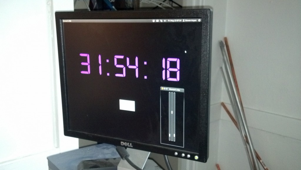
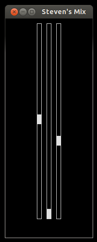
To control the relative mix of these signals, I programmed the mixer below in python 3. The first fader controls the master mix; the second fader controls the audio signal from only programs on my desktop computer; and the third fader controls the signal on the line in.

To make the faders, I used the tkinter module and created a Fader class, which inherits from tkinter’s Scale widget. The constructor for this class creates a Scale with the minimalist design shown, and it also gives Fader objects control over a Mixer object, which is described below. The Fader class also adds a changeVolume method, which is called when the user moves the fader on screen. The changeVolume method sets the volume of the Mixer object attribute based on the height of the fader.

screenshot-cropped-edit

The Mixer object comes from the alsaaudio module, which can be found here. From the site, “This package contains wrappers for accessing the ALSA API from Python.” A Mixer object represents a way to manipulate controls for different ALSA lines where each line carries a different signal. The names that ALSA gives to the lines that I’m controlling are “Master” for the master mix, “PCM” for the mix coming out of software on my pc, and “Line” for the mix coming into the line in port.

The changeVolume method also does some math before adjusting the mixer. The position of the fader on screen maps linearly to a height value read by the Fader object. However, the perceived intensity level of sound is logarithmic with respect to its amplitude. To compensate for this, the changeVolume method curves the input from the fader before it applies it to the mixer. As a result, moving the fader at low volumes causes the mixer volume to change slightly, and moving the fader at high volumes causes the mixer volume to change dramatically, so the intensity out of the speakers sounds linearly increasing from bottom to top of the fader.

This mixer is pretty minimalist, but in the future it would be cool to have something more like the native mixer in Windows 7, which not only shows the fader but also bars visualizing the volume of the signal for each input.

Now, I’m working with some temperature sensors to regulate things in my room and display information about temperature on my screen, too. I’ll keep you updated!

If you walk into my room, you might see an interesting interface on my desktop:

2012-05-25_07-54-35_738-resized

I’m referencing the clock and the mixer, not Unity :p

These are two tools I made freshman year: a unique clock and an audio mixer. They run on my desktop, an old HP computer that I got off reuse. I made the clock first, so I’ll describe it first and save the mixer for a later post.

Background

Laypeople count “1, 2, 3, …”; programmers count “0, 1, 2, 3, …”. However timekeepers must be really terrible at counting because, for each am or pm period, they count “12, 1, 2, 3, …”! A couple standards for time exist around MIT, whose students often require timekeeping that is unambiguous even during the night hours.

Take for example Random Standard Time (RST), created to accommodate the waking hours of residents of Random Hall. In RST, each day starts at 6:00 and ends at 30:00. 6:00 RST aligns with 6:00am of that day while 30:00 is actually 6:00am the next morning. This way, residents can avoid the inconvenience of day changes at midnight.

Another example is the practice of adding a delay to events around midnight to avoid the confusion of day changes. Suppose, for example, I have a pset due 9am Wednesday. If I want to tool with my friends 7 hours before the pset is due, it is ambiguous what day to tell my friends to join me. To employ the delay strategy, I would say to meet 11:59 Tuesday night, which falls unambiguously under a certain 24 hour period. Then, I would add that we should be 2 hours late, thus meeting at the desired time. One alternative phrasing, meeting at “2AM Tuesday night”, sounds a lot like meeting at “2AM Tuesday”, which would allow far too little punting!

Because hackers are notoriously late, a 15 minute delay is sometimes called “Hacker Standard Time”, so the phrase “HST” can be implemented when using the delay strategy described above to concisely remove ambiguity for events around midnight.

Beyond these standards, there’s lots of cool ways to count time. One more practice listed in the Wikipedia article is to continue counting past 23:59 to express nighttime am hours as 24:00, 25:00, 26:00, etc, and this is the basis for my clock.

Besides timekeeping, RST also implies a system of datekeeping in which every day is still 24 hours but each day is shifted. However, the following rule is my favorite system for datekeeping: it is considered a new day if at least two of the following happen; otherwise, it’s still night of the previous day.

  • You eat breakfast.
  • The sun rises.
  • You wake up.

This system is great because, even if you pull an all-nighter, you are still guaranteed a new day as long as you eat something that you consider breakfast, and there is a new sun in the sky. Conversely, maybe you slept all afternoon, woke up at 11:00pm, and you’d like it to be tomorrow already so you can start feeling productive. Simply chug some cereal and you’re golden.

Implementation

Regardless of how you keep dates or time, I wanted to have some fun making a unique clock for my room, and I wanted to practice some of the Python I had been learning in classes like IAP’s 6.S189, so I made this clock. I used the tkinter and time modules for the first time. I also tried Python 3 instead of Python 2, which we used in class. The font is Digital-7, which is free for personal use. I made the font large enough that I could read it from bed without glasses, which is more than I can say for my cell phone or alarm clock.

screenshot3-edit

Example shot at 2:51pm

For my clock, the time starts synced with normal time when I wake up. Rather than am or pm, the clock runs from 0:00 to 23:59. Then, at midnight, it keeps counting up through 24:00, 25:00, etc until I press a button to tell it that I’m going to sleep. When I wake up, I press a button to tell it, and the clock re-syncs with standard time.

screenshot4

Example shot late in the night of 30 December; you can see in the top left that it’s actually 1:07am on 31 December

To do this, the program toggles a Boolean at midnight to indicate that the time is extended from the previous day. The “Going to sleep” button seen above disables this toggle, so the clock rolls over to 0:00 at midnight. A “Waking up” button, which appears in place of the “Going to sleep button” re-enables the toggle for the next night. The “Override” button seen above manually toggles the variable, and the “Close Clock” button closes the clock.

The "going to sleep" changes to a "waking up" button after being pressed

The “going to sleep” changes to a “waking up” button after being pressed

For my curiosity, I’d also like to implement a program that keeps a log of when I sleep. However, the interface for this would probably be more convenient on a phone or some device that I carry with me regardless of where I sleep, so a program on my desktop is not convenient. I plan to link this my clock to reset it remotely.

P.S. even if you’re away from your dorm room for winter break, you can still apparently ssh into your desktop and take screenshots: xwd -out screenshot.xwd -root -display :0.0

I’m making a blog about projects that I’m working on!

Right now, I’m working on a couple projects targeted at improving my living environment, so let me start this blog by describing my bed, a project for which I’ve gone through a couple iterations. I live in the dorm East Campus (EC) where people often return their institute bedframes and instead build their own loft beds for their rooms. I like how lofts increase the floorspace of a room, but I didn’t like how they crowd the headspace. With that in mind, last year I started designing a bed that would lay on the ground for sleeping and fold up against the wall during the day. I also had an idea to motorize it for convenience. I was also working under the constraint of using only lumber, which I could reuse from EC rush activities.

I started imagining a full mattress frame on which the mattress would rest where the frame would be very thin but still strong enough so that the mattress would not fall through if I tilted the frame on a side. I started drawing plans with slats against a piece of plywood, but I didn’t like how much material such a frame added. It would make the bed about twice as heavy, and it increased the thickness of the bed about 2 inches from the starting 7 inches of mattress thickness.

Instead, I realized the mattress had some strength itself, and I could support it without a full frame beneath it. I decided to instead frame the sides of the mattress in lumber and support the bottom with some kind of netting or else just a few strips of plywood. With that in mind, I made some plans:

For the frame, I used 4x4s on the short sides and 2x4s along the long sides. The lumber and mattress is shown in this drawing, but the netting underneath the mattress is omitted. I made this draft in SolidWorks.

121224-bed-down 121224-bed-mid 121224-bed-up

To fold up against the wall, I had the bed pivot on one side. I wanted hinges that could support on the order of 100 pounds, so I designed those pictured below. My intention was that, by cutting the beams at a curve, there would always be wood-wood contact between the frame and the hinge base. Then, the weight of the frame would be at least partially transferred through the wooden sides of the hinge bases rather than entirely on the copper tubing that I used as a pivot.

121224-hinge-cropped

Before building the frame, I printed some dimensions off of my drawings to help me make check my measurements, like those of the hinge base above. When I built it, I assembled it in parts: the hinges, the short pieces with the corner boards, and I left the long pieces unconnected. This way, I could hypothetically disassemble my bed into easy to maneuver pieces if I wanted to change rooms.

After I put the frame together, the mattress could actually stay in place just from the support of the boards in the corners and from the grip of the frame itself. However, I went ahead and tied the mattress in to keep it from slipping out of the frame in case of extra load pushing the mattress up or down. I used paracord.

2012-05-25_19-17-19_93-resized

To support the mattress from underneath, I simply tied a length of cord between the long beams of the frame. The middle vertical black line in the above picture is this piece of cord. I also used a dremel to cut a shallow channel in the side of the beams for the cord to rest in, which you can see in the picture below of the cord wrapping around the topmost beam.

2012-05-25_19-17-35_830-cropped

I also wanted cord pulling the mattress down into the frame to keep it from tipping out when I leaned the bed against the wall. However, I didn’t want the cord to get in the way, and I wanted it to be easy to unfasten the mattress to take off the sheets and wash them. First, I tied two lengths of cord around the uncovered mattress, which you can see as the left and right vertical lines in the earlier picture. I placed the bends for each length on the underside of the mattress for convenience. With the mattress on the ground, where the lengths of cord intersected the top edge of the mattress, I tied loops inline, 4 total. Then, I fastened each inline loop to more cord hitched to the frame such that the cord pulled the loops downward into the frame. I wanted small quicklinks, but I probably used slipknots as fasteners. Regardless, by unfastening these inline loops from the frame, I could easily remove the mattress from the frame. I could also remove the sheets, as explained below.

For covering the mattress, I first placed a foam mattress pad on top of the mattress. Then, I covered the mattress with a fitted sheet, and I cut 4 holes in the sheet for the inline loops to poke out. One loop is shown below. I stitched around all the holes to prevent the fabric from degrading.

2012-05-25_19-17-44_450-resized

Unfortunately, the frame was grunged over the summer, so I don’t have much media of the final product beyond some low-res video. However, I was satisfied with the action of the hinges, and the bed was light enough to lift with one hand. Here’s a shot of the full bed! I stitched it together from frames of video, so excuse the grey space.try9-edit-resized

In a later post, I’ll tell you about my newer iterations of this project!