If it ain’t broke, don’t fix it. As I wrote in a previous write-up, a clock turned out to be a great gift idea for a very special person, so I decided to make another for the same person a couple years later. To contrast the wooden, analog clock I made before, I decided to make one covered in LEDs. Same as before, my vision was to create a 12-point mandala. Although this clock has no hands, the 12 points still allow it to display time in a way that is reminiscent of an analog clock, as described in the Patterns section below.
In this post, I’ll walk through my design process from initial sketch through hardware development and programming. At the end, I have provided links to the design files and source code. I also used this project as an opportunity to learn KiCad and to learn and practice the philosophy of what makes a readable schematic, so I’ll mention that as I go on. As a disclaimer, I made this back in 2019, so some libraries etc might be out of date.
Initial Sketch
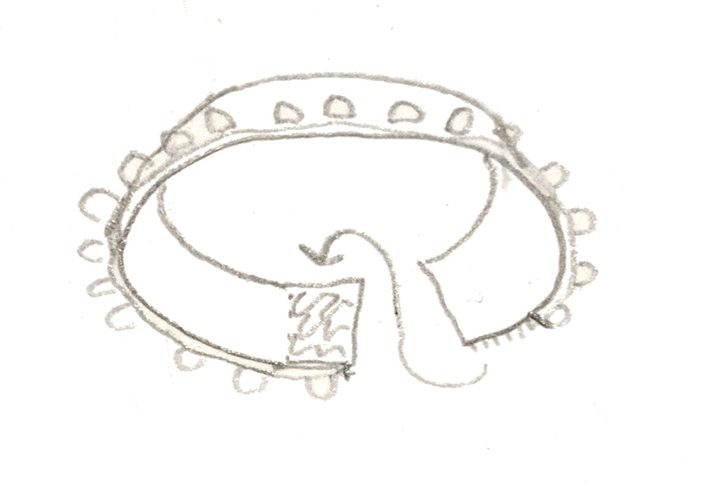
My first step was to sketch out what I wanted the clock to look like and what I wanted the system to look like. As I mentioned, I wanted to make a 12-point figure, so I used this website to sketch some rotationally symmetric shapes. I wanted at least a little more detail than a 12-point star, but I knew too much detail would not be possible to cover with LEDs, so I settled something with 6 big petals, 6 small petals, and a broken ring around the middle as shown below.
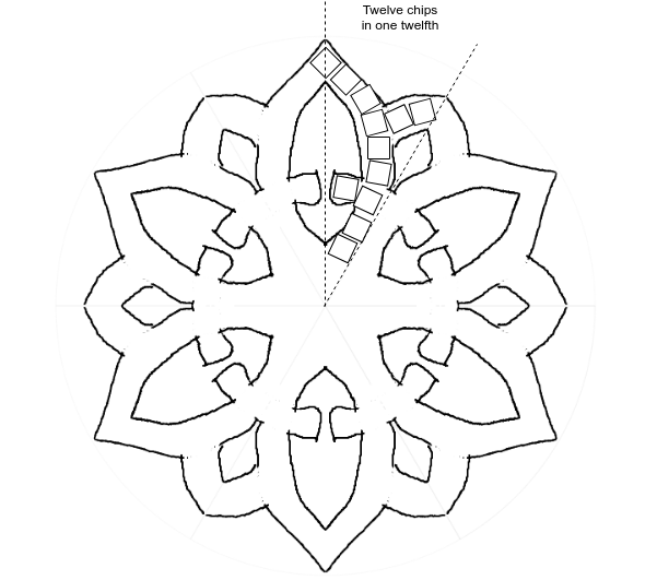
Part of my vision was to have all the LEDs on one side of the piece with no other electronics visible, for a clean look, so I next looked into how many LEDs I could cram onto the outline I made. I exported my outline into draw.io, and, using some squares set to common sizes of RGB LED modules, and assuming a ~6 inch wide piece, I took a guess at how many I could fit in the space, as shown in the image above. Although I guessed each twelfth of the shape could fit 12 LEDs, it turned out to be a squeeze once I started routing, so I later reduced it to 11.
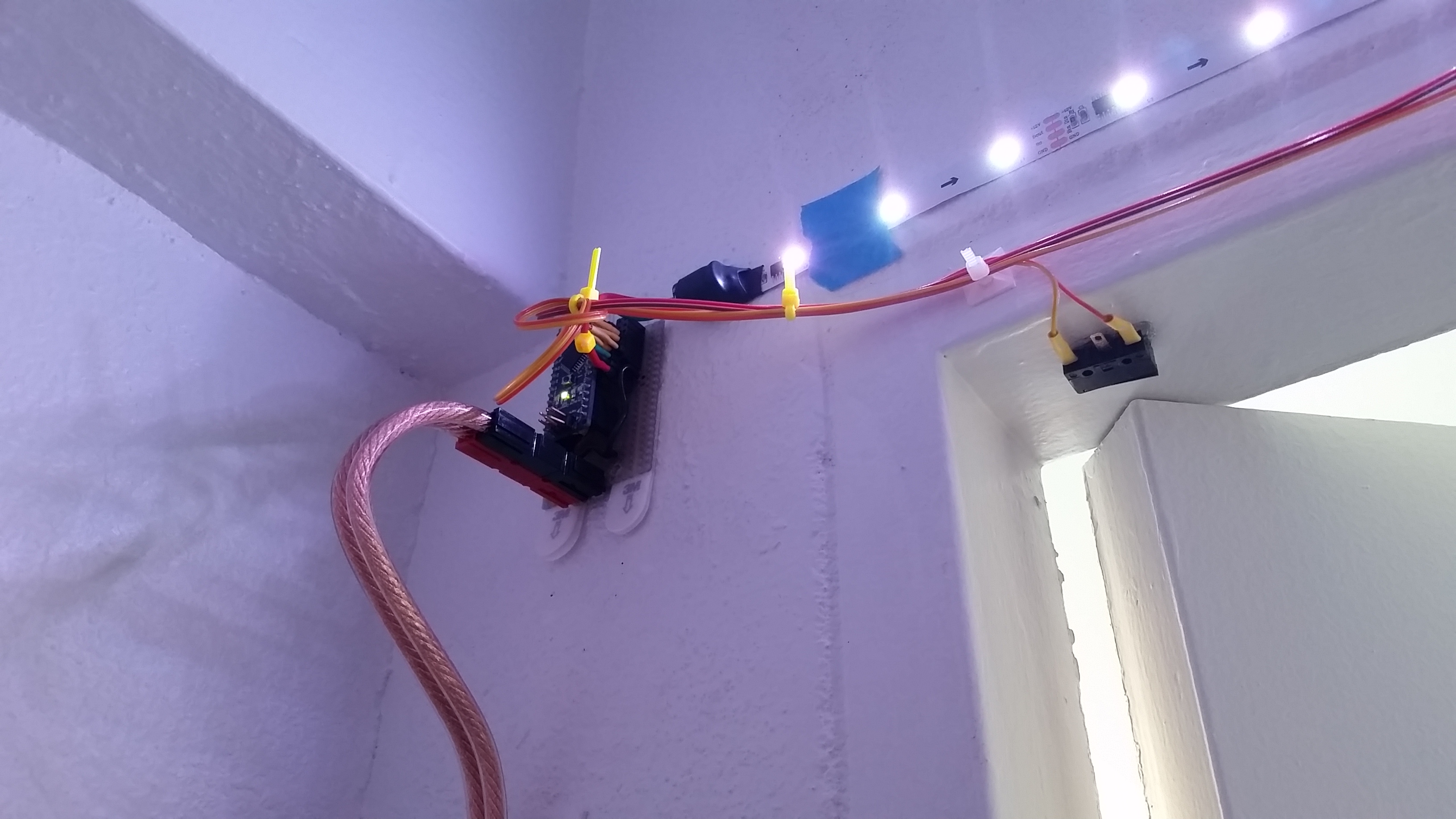
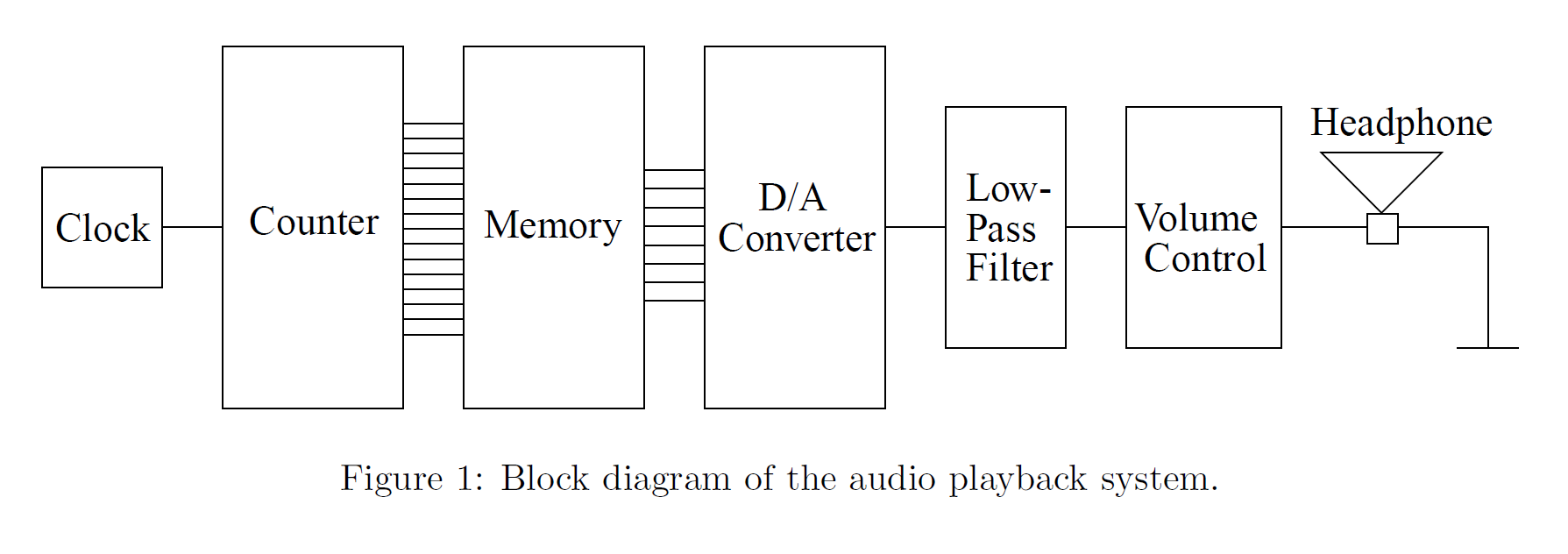
As shown below, I next sketched a block diagram of what the electrical system would need: a single chain of LEDs snaking around the board, a microcontroller to send the patterns, some buttons, and a battery-powered RTC to avoid losing the time when the device was unplugged. For the microcontroller, I decided to use an ATMEGA328P-AU, the same as on an Arduino Nano, specifically so that I could flash it with the Arduino bootloader. I wanted the piece to be user-friendly including if the user wanted to add patterns or fix anything, and I figured this would be the most convenient way to allow this.
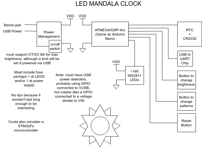
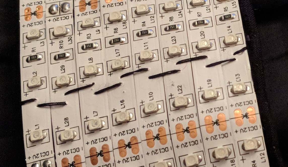
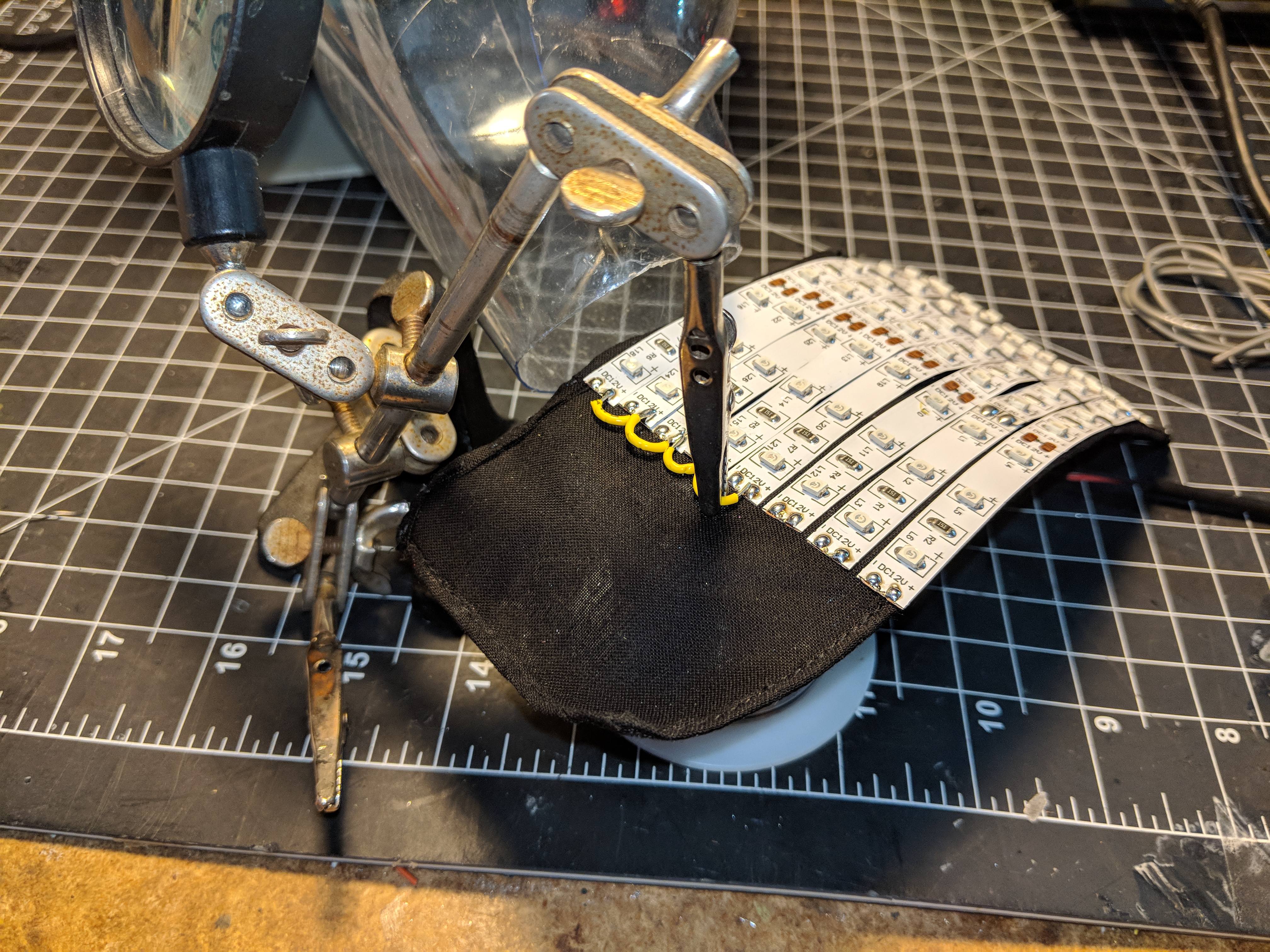
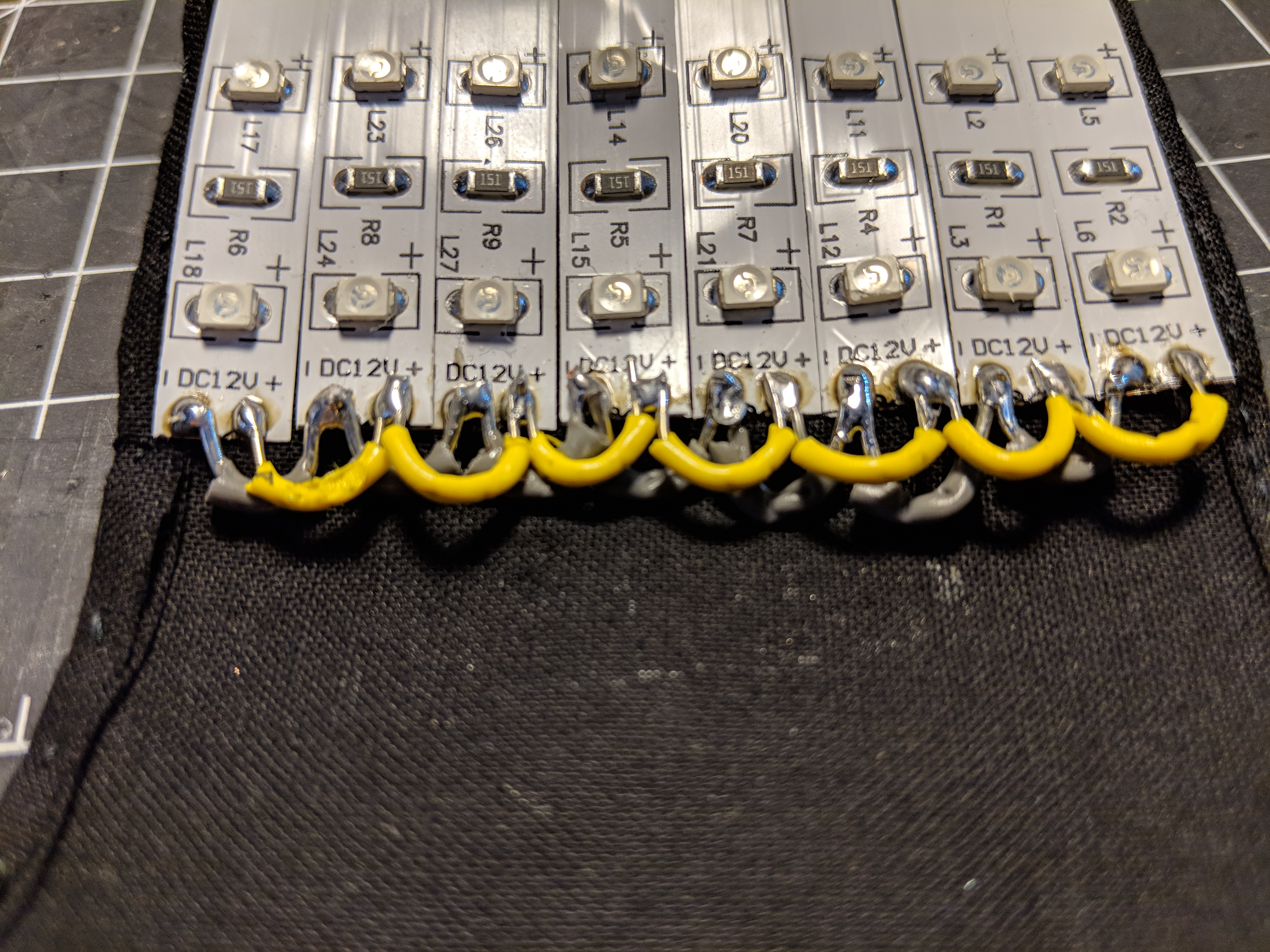
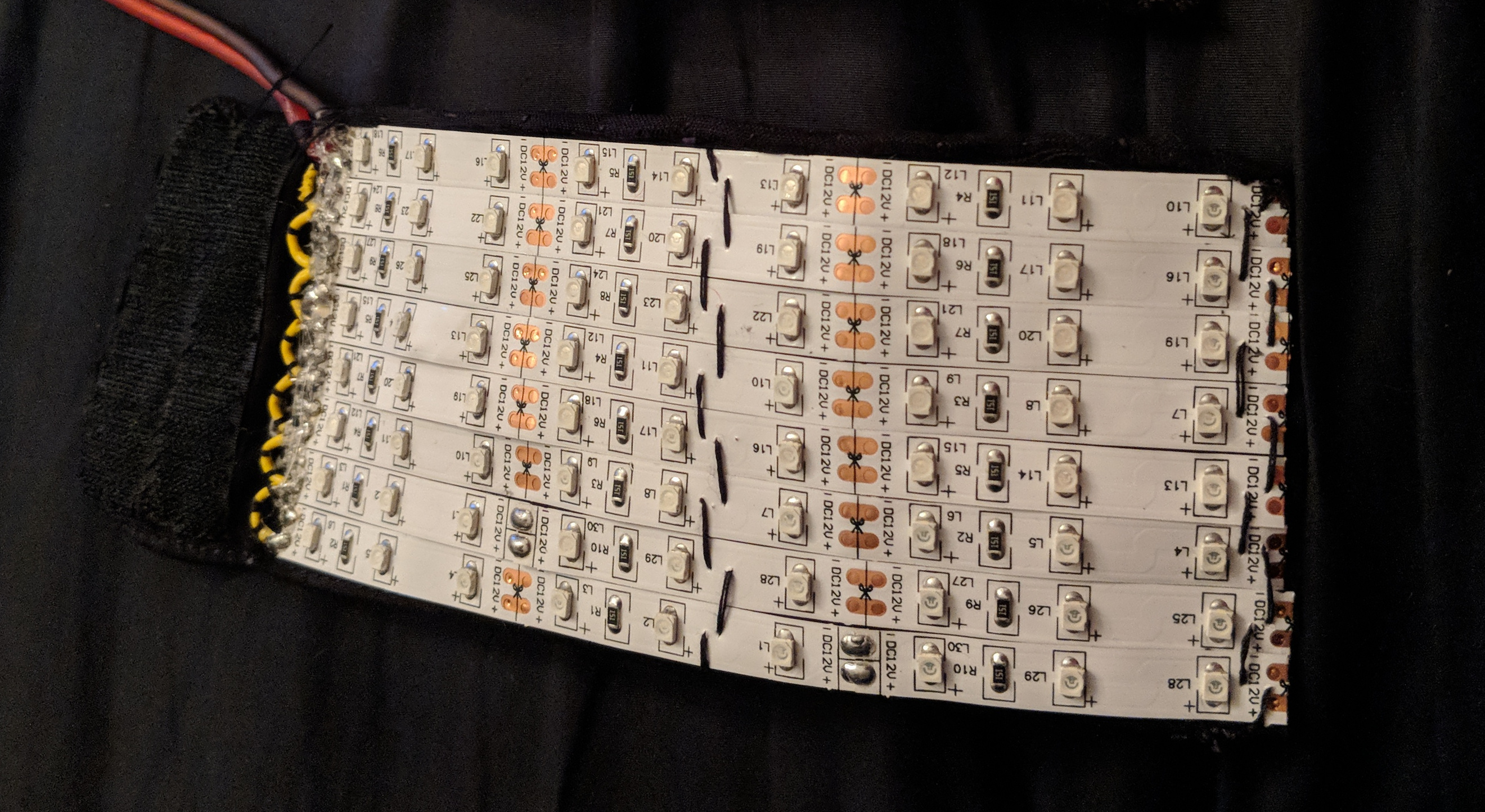
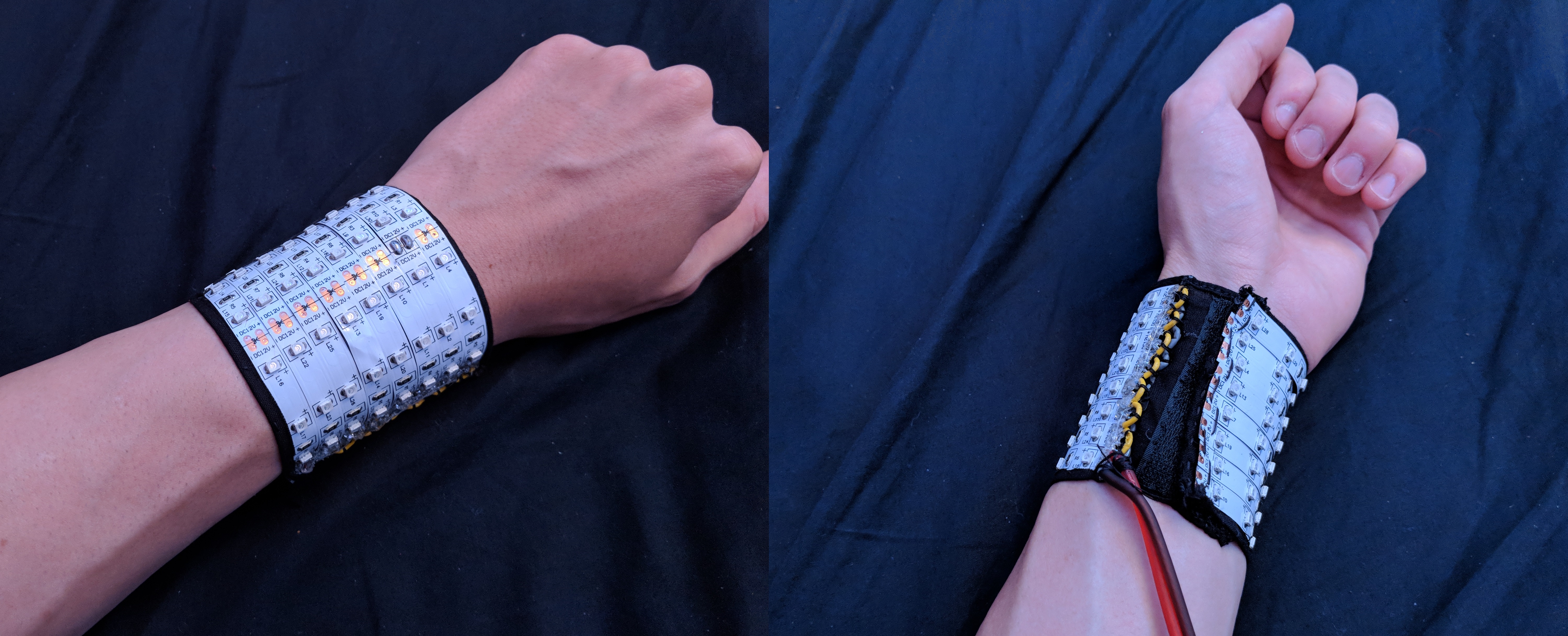
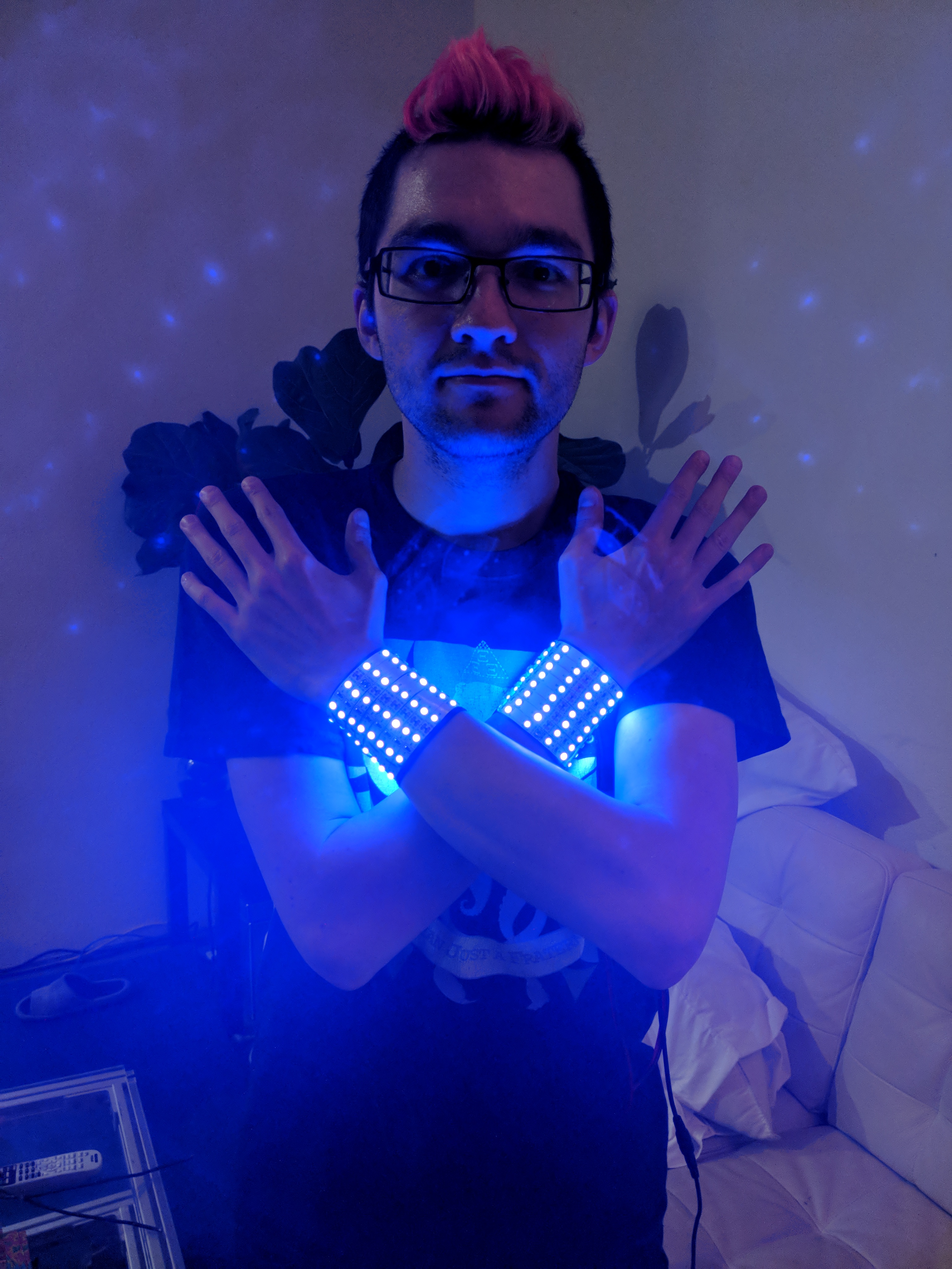
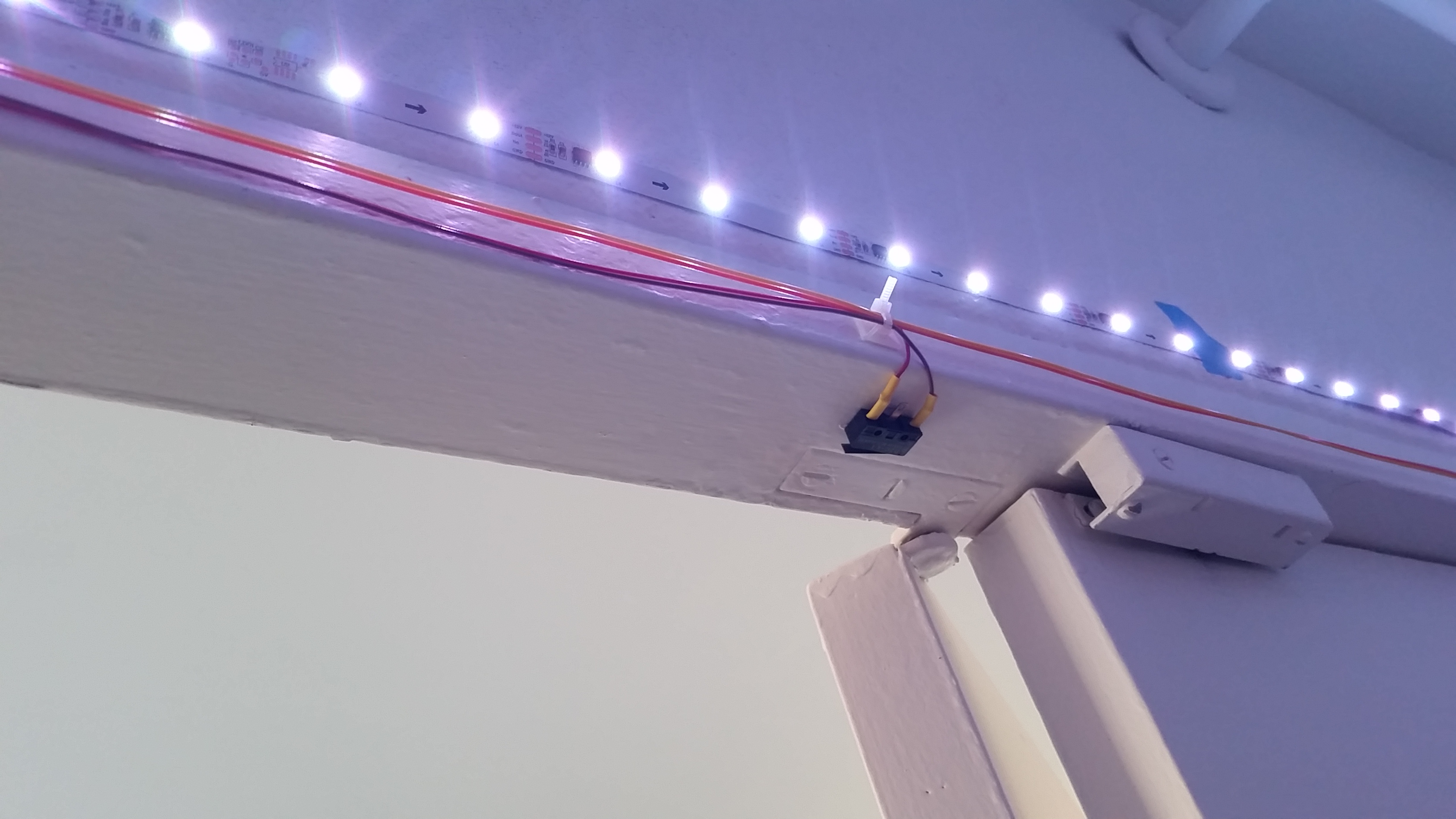
Based on some experimenting with an LED strip, I found this many LEDs to be super bright. As a result, I decided to power them with a fairly low voltage of 3.3V. This is actually below the minimum specified in the datasheet for the WS2813 (the LED I ended up using), but I found a large majority of the chips still worked at 3.3V, which was good enough for a one-off project. Lowering their maximum brightness also had the benefit of decreasing the step size of the brightness levels, making the patterns smoother. In addition, this allowed me to use the same 3.3V supply for the LEDs and all the logic chips on the board.
Schematics
With the big picture in mind, I started on the electronics. For the components themselves, some notable choices I settled on were:
- WS2813 for the LEDs themselves — similar to WS2811 and WS2812 that I’ve used before, and they include a redundant data line so that, if one chip fails, the next chip in the chain still works.
- DS3231M for the RTC — its crystal is internal to the IC itself along with a temperature sensor, which allows it to compensate for temperature drift, making it much more accurate than a regular RTC.
- MPM3620A, an integrated buck converter module, for the 3.3V power supply on the board — I find modules like this to be super convenient for prototypes.
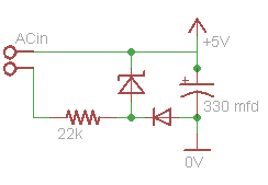
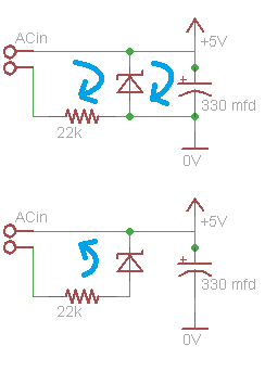
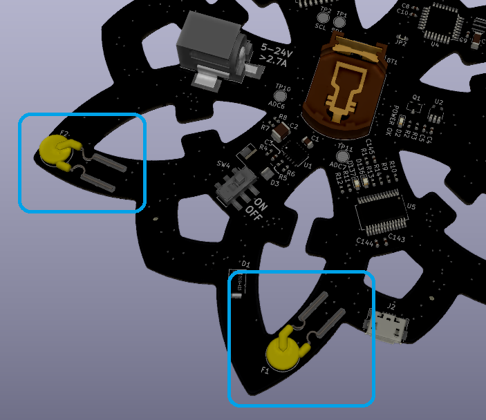
I also used an input-protection paradigm that I kind of like: a fuse followed by a transient-voltage-suppression (TVS) diode, as shown in the following snippet. The fuse (F2) protects the external power supply in case the LED clock has a short; it is sized to be big enough that it won’t blow in normal operation, but it will blow before the external power supply is damaged. On the other hand, the TVS diode (D3) protects the LED clock from the external power supply in the case of excess voltage being provided.
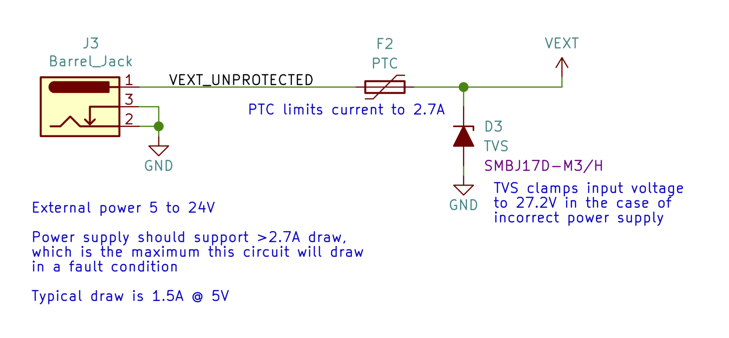
TVS diodes work by becoming much more conductive above a certain voltage, making it very hard for the external supply to raise the voltage past that threshold. A TVS diode is typically used for transient spikes in the external supply, but, as long as the TVS diode is rated for more current than the fuse, it will even protect against the user connecting a supply whose voltage is too high in this scheme.
In my case, I used a positive temperature coefficient (PTC) resistor as the fuse. When PTCs heat up from high current, their resistance shoots up, acting like an open circuit, but they conduct again when they cool down. As a result, they act like an automatically-resetting fuse, which is more user-friendly than a regular fuse.
I think I’ve seen this scheme in automotive designs, and I also saw it is used on the Ruggeduino (see Method #1 discussion on this page).
Anyway, you can read through my full schematics attached at the end of this post. In the course of bringing up the board, I noticed a couple errors in the design, so I actually updated the schematics to point them out. I was able to work around all of them for this iteration, but you would want to fix them before reusing the relevant parts of this design.
Schematic Philosophy
In the course of making the schematics, I spent a good deal of time thinking about what makes a good / readable / useful schematic — here is one article I liked on the subject. Let me know your opinions on what makes a good schematic. Making schematics is an art and requires inspiration.
My schematics are done in the hierarchical style (i.e. starting with a top-level page), and some practices I mostly followed were:
- Each page reads left-to-right: inputs on the left, outputs on the right.
- Each major integrated circuit gets its own page.
- Comments are succinct but answer the questions people would have when looking at the schematics.
One thing I didn’t like about KiCad (at least the version I used) was how it handled re-using schematic sheets (i.e. what Altium calls “multi-channel design”). In my case, I didn’t want to draw out all 132 LEDs, so I drew one twelfth of them on a sheet. Then, I created 12 duplicates of that sheet in a higher-level sheet. KiCad was able to do this just find, the only downside is that the exported PDF includes 12 pages that are almost exactly the same except for incremented part designators. I feel like there ought to be a more user-friendly way to tell the reader that the circuit is repeated 12 times without actually printing 12 near-duplicate pages. For example, there could be a single page with placeholders for the designators along with a table of the 12 different designators used in each copy of the circuit.
Layout
As for the layout, I took my sketch from before, re-drew cleanly it in a Solidworks sketch, and exported the DXF to import in KiCad. I routed the whole thing on 2 layers, which made the board quick to manufacture and less expensive than a 4-layer board. This worked fine except for the USB lines, which ended up only working intermittently, I presume because I didn’t know much about controlled impedance or return paths at this point. In the end, I tried a bunch of USB cables and eventually found one that worked reliably.
Routing is always my favorite part of PCBA design, and this project was especially was fun given the 60 degree angles instead of the usual 90 and 45 degree angles. I rotated several components to 60 degrees to fit on the arms, and I did a lot of free-angle routing in the narrow regions of the arms. Unfortunately, KiCad also didn’t have good support for re-using routing (again, “multi-channel design”), so I ended up routing one arm’s worth of LEDs, then writing a Python script to copy the routing to the rest of the arms. Tediously, my script had to modify the text of the layout file directly because the version of KiCad I was using didn’t support scripting within the program itself, but maybe you can do this kind of thing from within KiCad now.
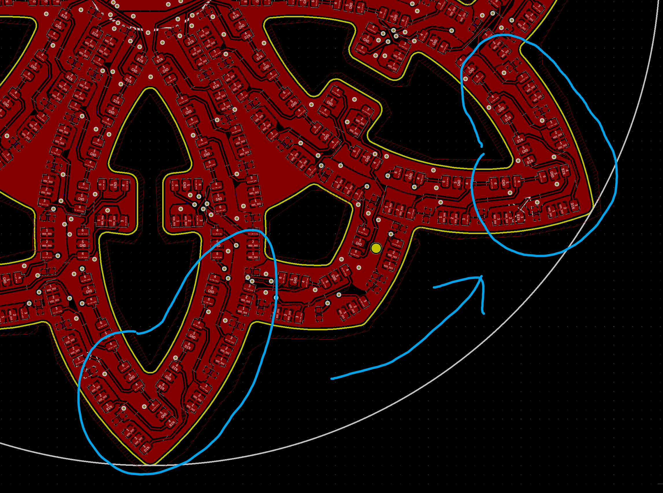
When I was picking components, I was careful to pick only surface-mount components because I knew one side of the board would be covered in LEDs, leaving no room for leads. However, for the PTC fuses, I could only find through-hole parts of appropriate amperage. As a result, you’ll notice I got creative with a new surface-mount footprint for these parts.
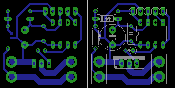
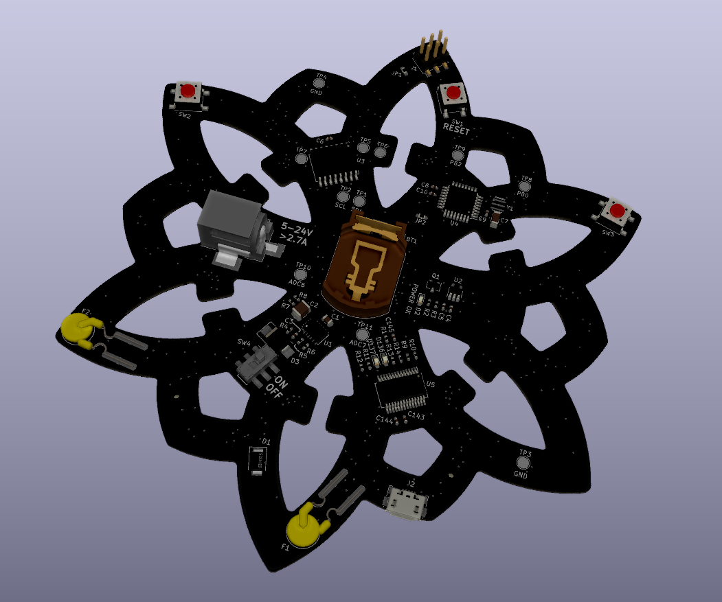
Anyway, KiCad, like other EE CAD software, provides some neat 3D renders of your PCBA, so here’s a look at the finished design:
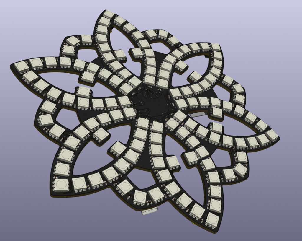
Front 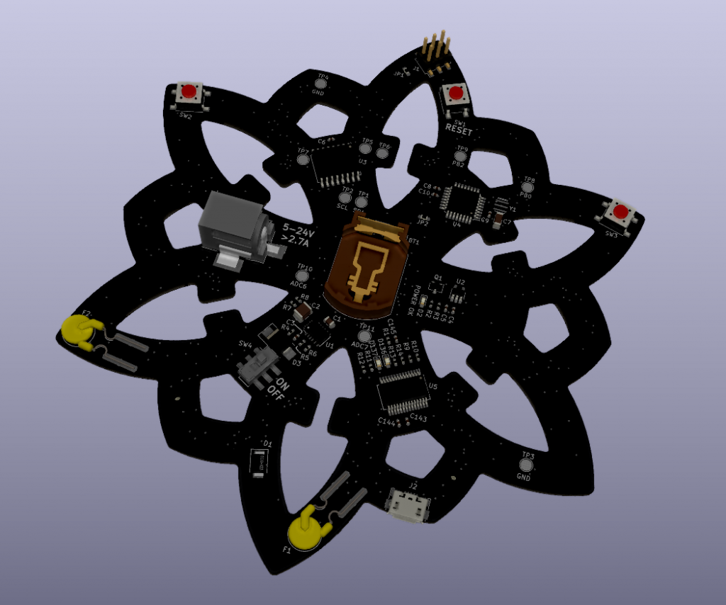
Back
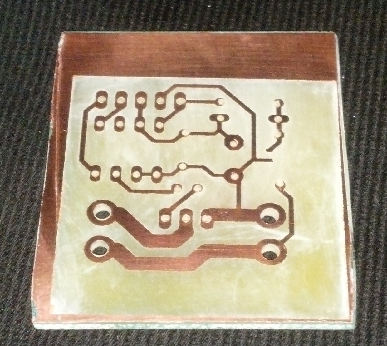
Manufacture and Assembly
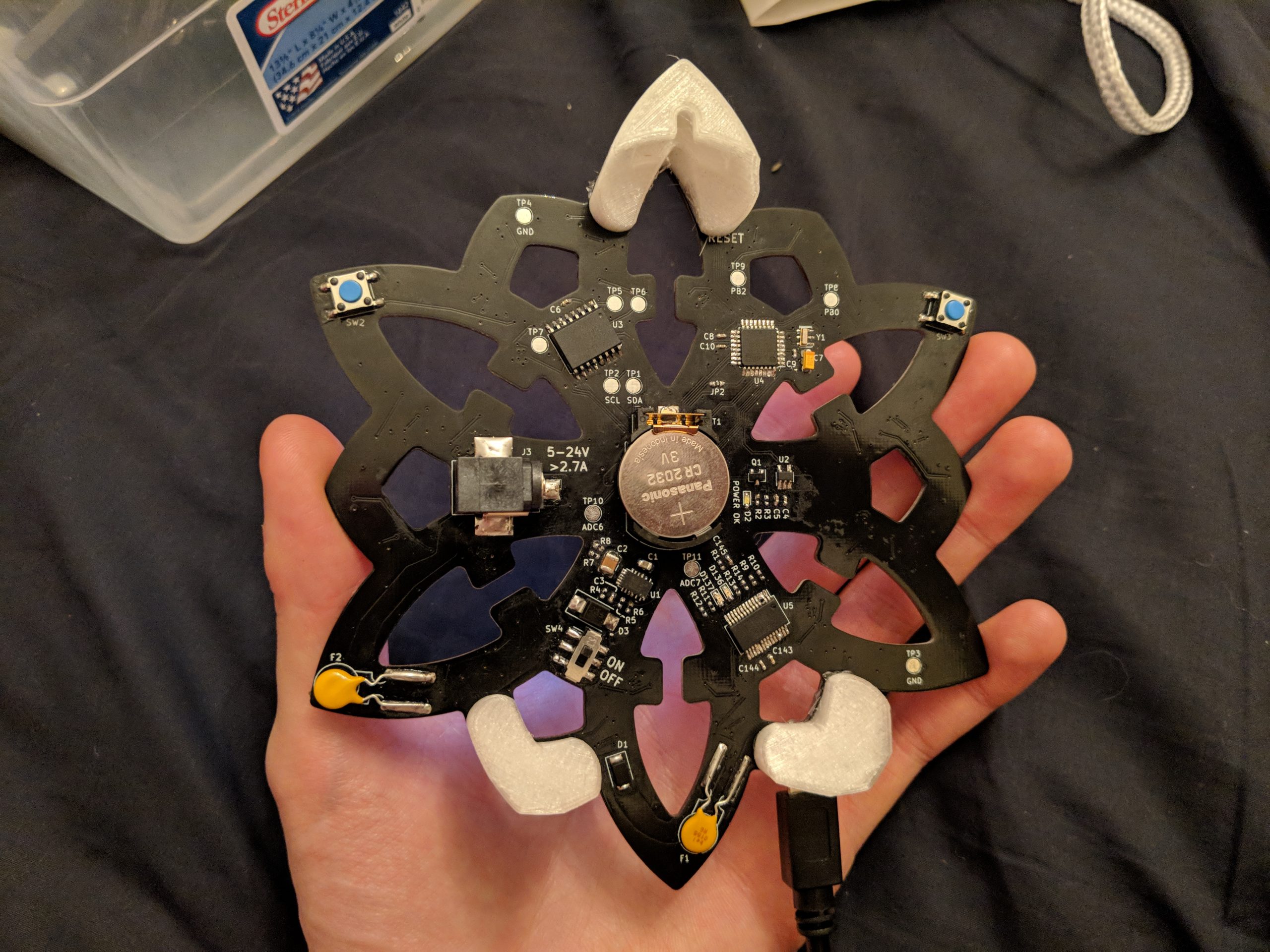
After I laid out the circuit, I had the PCB manufactured by PCBWay, and I installed the components myself. As noted in the schematic errata, I ran into a couple issues as I assembled and tested each portion of the circuit, but I was able to work around all the issues. For the microcontroller in particular, I had trouble flashing the Arduino bootloader and ended up just desoldering the chip from an actual Arduino and using that.
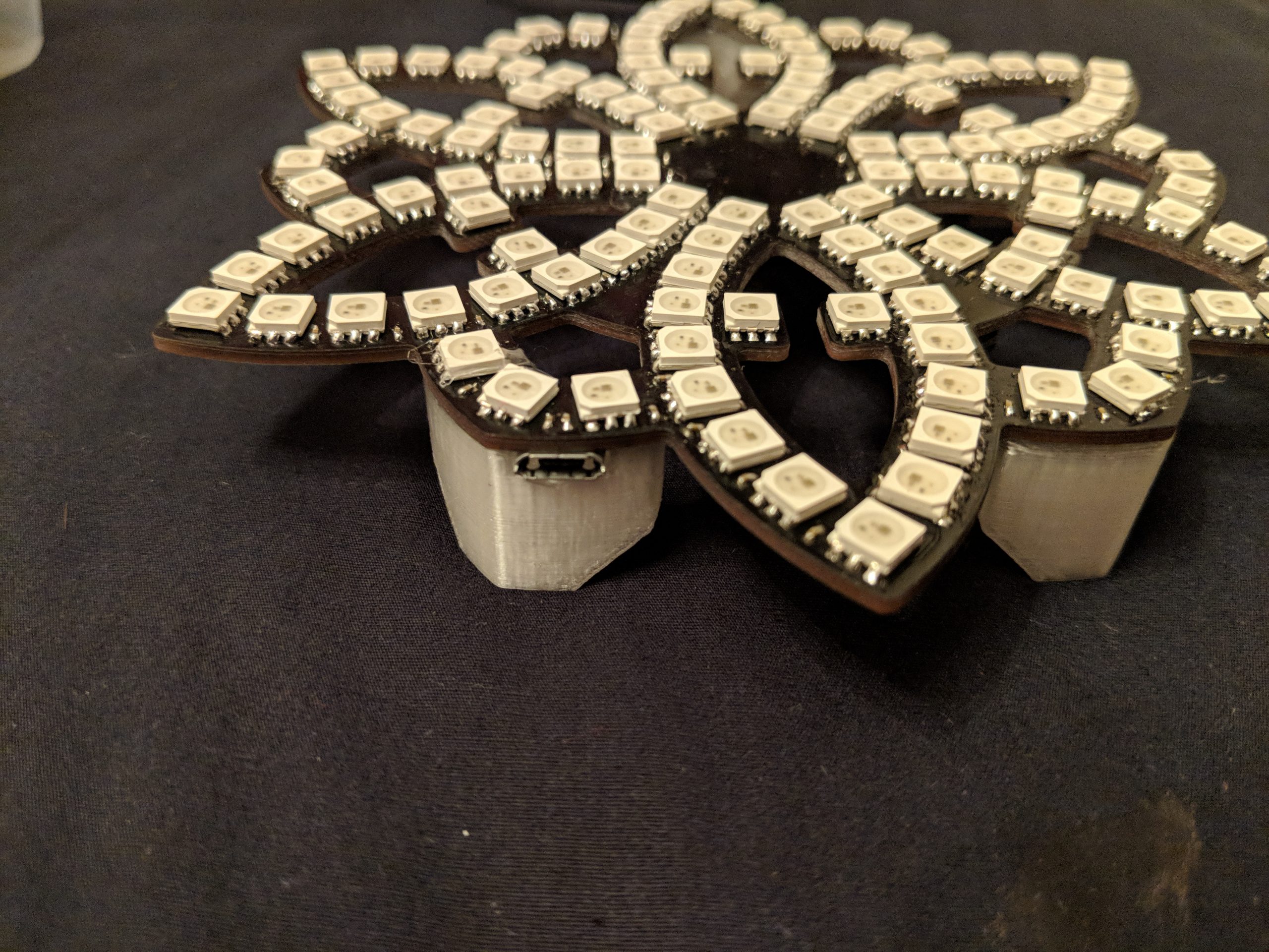
After I installed everything, I also whipped up some 3D-printed standoffs for the board, pictured below.
Software
As far as the software is concerned, this board is an Arduino connected to an LED strip, as mentioned earlier. As a result, the source code is an Arduino project, and it consists of one file for the main loop, one file for the LED patterns, and a couple auxiliary files. Some libraries I used include SoftPWM (for animating the power LED), RTCLib (for the RTC), and Bounce2 (for debouncing the buttons).
For the LED patterns themselves, I wanted to make it easy to highlight the layers of the geometry: the big petals, the little petals, the ring, the outline, etc. I accomplished this by listing the LEDs that made up each of these groups. For example, the middle ring consists of 24 of the LEDs in the entire chain: the 3rd, the 4th, the 17th, the 18th, etc. Then, when I wrote patterns, I could iterate over all the LEDs in one group and apply one color, and iterate over a different group with a different color.
All the patterns are implemented as functions that generate a frame based on the current time. For example, if I wanted a pattern that switches the LEDs on and off each second, I would write a function that checks if the current time is an even second (in which case it turns the LEDs on), or an odd second (in which case it turns the LEDs off) rather than writing a function that calls delay(1 second) repeatedly.
One challenge of generating these frames is that the RTC only provides the current time to the nearest second, which would make for very slow and stuttery patterns. To get around this, I implemented a function that estimates current time to the nearest millisecond. It does this by checking how much time has elapsed on the microcontroller’s internal clock since the last change in the seconds’ value of the RTC time. Long-term, the microcontroller’s internal clock accumulates much more drift than the RTC, but it works great for getting sub-second resolution like this. This is in the file now_ms.ino.
Each pattern function also is passed the current brightness level (0-10) as a guide for how bright to make the frame. In the main loop, one button adjusts this brightness level, and the other button changes what pattern is displayed.
Patterns
If you’ve read this far, you’re probably interested in what the patterns are, and how to read the time off of any of them! Here’s a table. Some of the patterns convey the time while some are just aesthetic. I felt like, since anyone can just check their phone for the time, it was more important that each pattern be beautiful or interesting than be a strictly useful timepiece.
| Pattern | Description |
|---|---|
| Analog Clock | Shows the time like an analog clock: the innermost ring of LEDs is the point of the hour hand, the middle ring is the point of the minute hand, and the outer ring is the point of the second hand. |
| Rainbow Cycle | A rainbow cycle moving one direction over all the LEDs paired with a white pulse moving the opposite direction over the big petals |
| Lava | Red and white pulses that move over the entire chain of LEDs |
| Rainbow Fade + Heartbeat | The entire piece fades through the rainbow every 24 hours while the middle ring pulses white every 3 seconds. |
| Sparkle | Random white flashes over the entire chain of LEDs |
The following video shows each of these patterns.
Files
Here are the schematics, CAD files, and software for reference. Enjoy!
- Schematic for download: 190328_schematic_with_errata.pdf
- Link to hardware repository on Github (includes models for standoffs) — As a heads up, I wasn’t originally tracking the custom symbols and footprints, so I just added them in a recent commit. All the 3D models are included, but some of the paths are messed up.
- Link to software repository on Github