I’ve been learning to spin Poi with the MIT Spinning Arts Club since freshman year. Poi are tethered weights that a performer spins to create cool effects and illusions.
A variety of props can be used at the ends of poi leashes. One interesting prop I’ve found is an array of LEDs. By alternating which LEDs are active, the performer can create cool patterns. This is sometimes called pixel poi or LED poi, and you can see very nice commercial ones available here, here, here, and here. Along similar lines, here‘s a hacker who attached a persistence of vision display to a string to create a pixel poi effect.
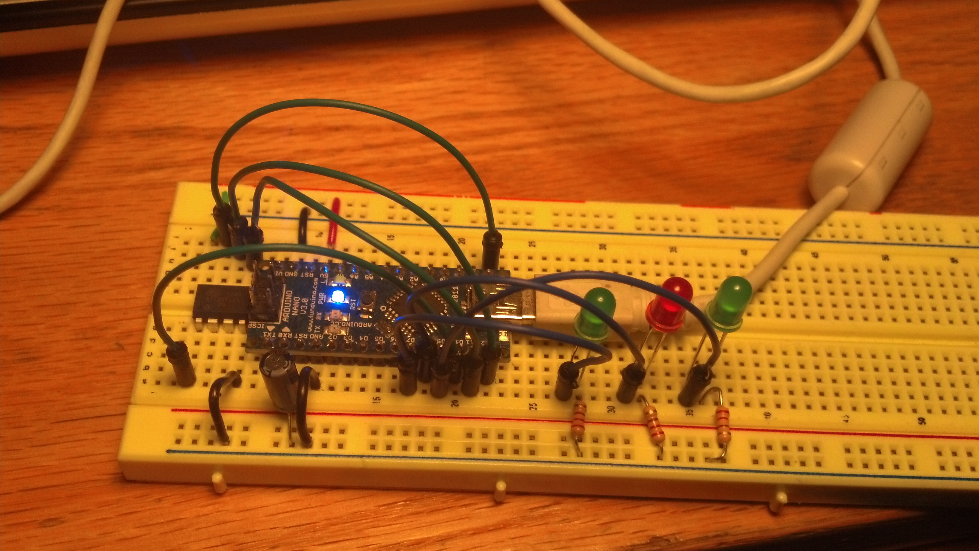
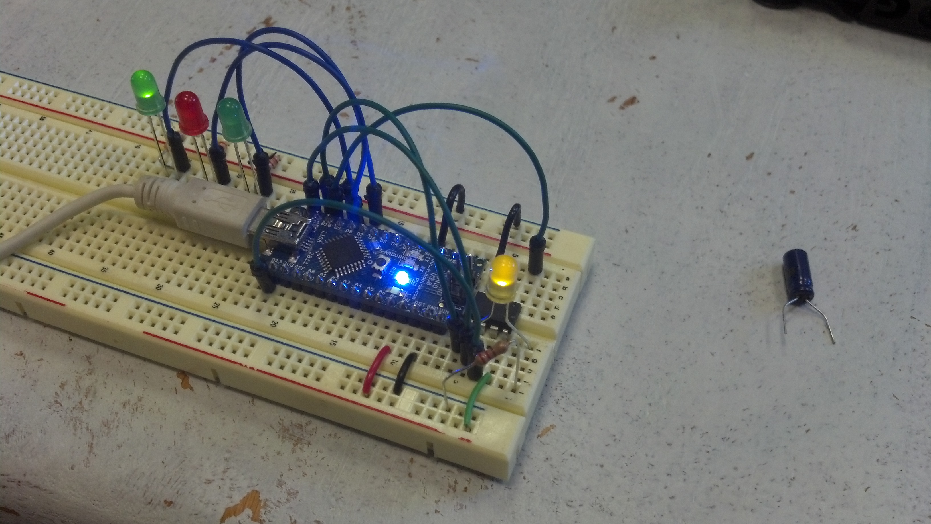
Images on the above sites have long-exposure pictures of the products to show their patterns traced out over big arcs. However, the effect shouldn’t be confused with the persistence of vision (POV) effect and POV displays, which would require spinning poi at more than 25Hz, which is about an order of magnitude faster than I can spin poi. I decided building some of these would be a good exercise to gain experience building cool things with circuits, and I also had some ideas for improvements. So far, I’ve created a small array of LEDs that I control with an arduino, and I’m working on finishing a poi. For the physical construction of the pixel poi, I plan to use about 15″ of 3/4″ polycarbonate tubing per poi. My plan is to house the LEDs and some circuitry inside while wires run up a short leash to the grip. Inside the tube will be a slack column of wires, LEDs, and circuitry tied to a pretensioned piece of cord to prevent loading the leads of the components. Above the grip, I’ll have a microcontroller and battery attached to each wrist. Long term, I plan to house all the electronics in the poi themselves, but this is more convenient now. As for the circuitry, I acquired two arduino minis, one for each poi. I also have a bag of RGB LEDs, and I plan to use 16 pixels per poi, where each pixel is probably 1 LED. To control the LEDs, I’m using some PWM drivers ICs, specifically the 16-channel TLC5940, which I hear is popular for this purpose. To control 16 RGB pixels, I’m using 3 chips. For now, I’m using some AA batteries to power the system. Before I started assembling the poi, I created a scaled-down circuit of one arduino and one 5940 driving 16 RGB LEDs on only one channel. I used the tlc5940arduino library, and I could drive the LEDs with various patterns. Shown below is a picture of a Knight Rider pattern in which a dot travels up and down the row of LEDs. The dot spans a couple LEDs, and, based on its direction of travel, it’s brightest at the front and dimmest at the rear, demonstrating how driving LEDs by PWM can produce a range of intensities.
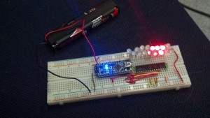
Here I’m just using one 5940 to drive only the red channels of 16 RGB LEDs.
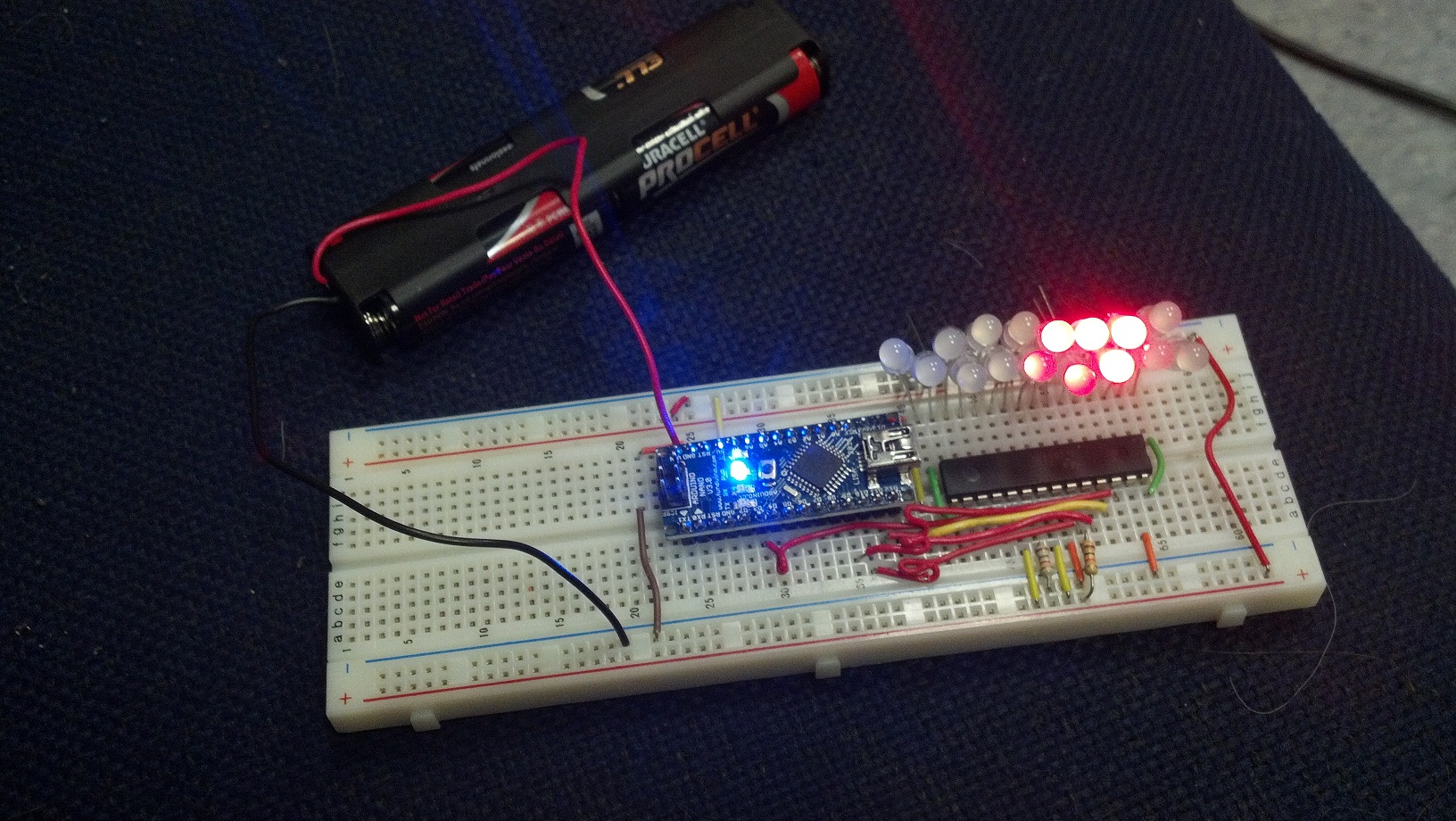
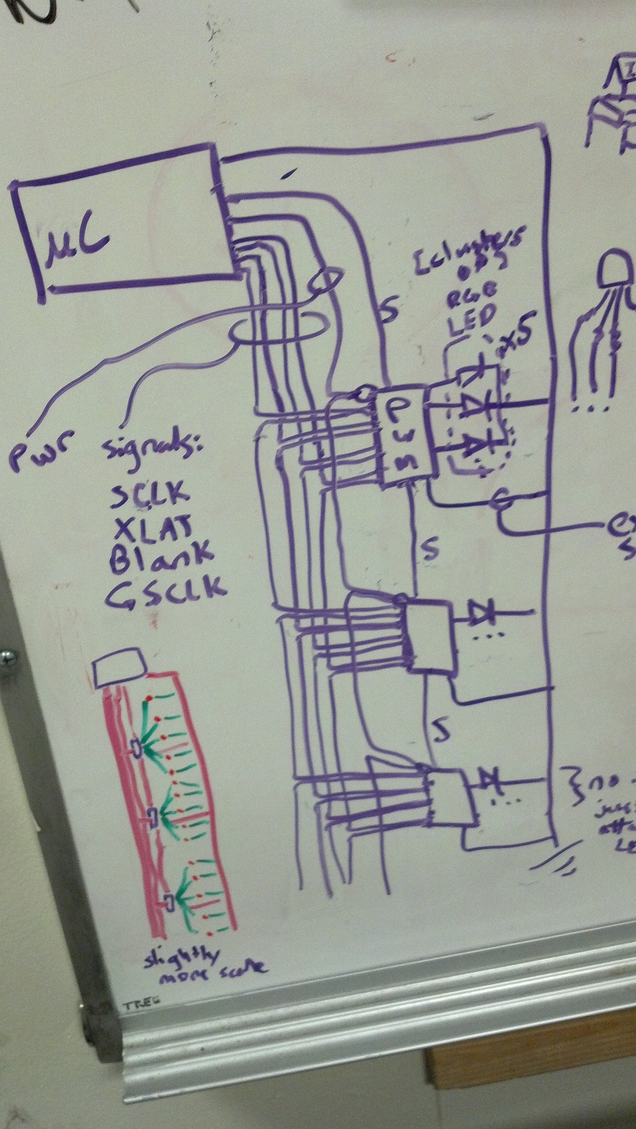
I also created a checkerboard pattern on the LEDs. The pattern alternated faster than 25Hz, so it appeared like unblinking LEDs when the breadboard was static, but waving the breadboard around revealed blinking LEDs. Next, my plan is to add more 5940s as well as lengths of wire in place of the breadboard to create the full poi. A whiteboard diagram shows 7 wires that travel down the tube. 5 are signals for the 5940, and 2 are power. The LEDs are placed between the output channels of the 5940 and ground.
In purple, this diagram shows wires between the microcontroller (µC), the 5940 PWM drivers (PWM), and the LEDs. Bottom left in red and green is a sketch showing the drivers and LEDs spaced evenly along a column, drawn to estimate how much wire I needed.
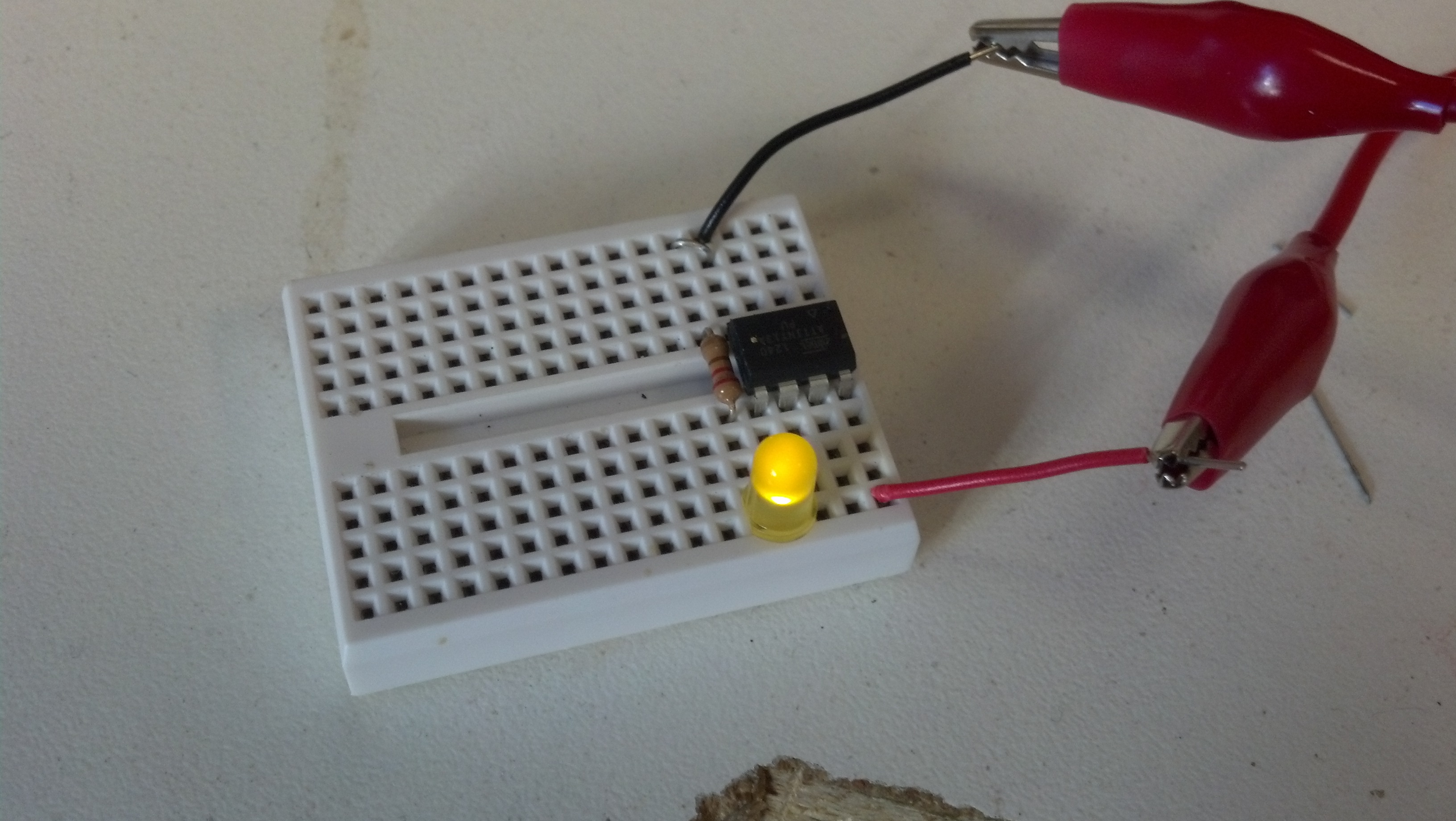
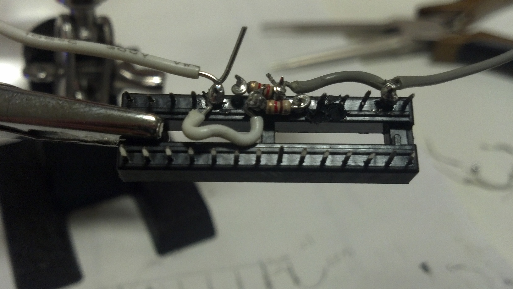
However, this plan requires soldering every LED pin and every 5940 pin, which is time-consuming. Shown below is a 28 pin socket, which I’m soldering in before inserting my actually 5940. At this point, I’ve soldered the input signal wires for about 3 sockets, but I haven’t yet started on the LEDs or the 16 output channel wires on the sockets, and I’m considering using instead a preassembled strip of LEDs for to expedite this.
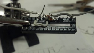
Some pins here have resistors connecting them to generate proper voltages to control the chip.
I’ll keep you updated on my progress. Beyond a cool prop, I’d also like to use onboard sensors to gather data about speed, acceleration, and relative motion between the poi. Then I could use the sensors to control the patterns themselves or to create a musical instrument controller.