Also known as the “Sketch as Fuck Lamp Dimmer” per my friend Eric, the design originating from this application note in general has the usual lamp dimmer topology: a zero detector, a timer, and a triac. These three components implement phase cutting, specifically the triac performs phase cutting on AC current from mains supplied to a load. The first two components, the zero detector and timer, are both implemented in a microcontroller, the subject of the application note.
However, this circuit is unusual in terms of its logic power supply, whose ground is not connected to the neutral of mains. Rather, the 5V node is connected to the hot wire of mains, and the 0V node is constructed 5 volts below that wire.
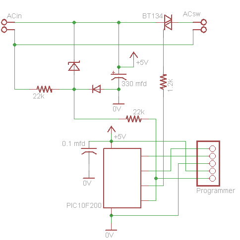
I designed my schematic in Eagle. Though not labeled, for space, the diode is a 1N4448, and the zener is a BTZ52C5V6T-TP.
One consequence of this is that, while plugged into mains, the logic of this circuit cannot be connected to any logic that is grounded to the neutral of mains unless the signals have some isolation. For example, I couldn’t connect connect my PIC programmer to the circuit while the circuit was plugged into mains without something exploding! To get around this, I plugged my circuit into an isolation transformer prior to mains during the latter part of programming the circuit, after I had confirmed my circuit functioned correctly electrically. As discussed later, this design is necessary to achieve proper biasing in the circuit, and you can see this power supply in other circuits as well–for example the application note for another lamp dimmer from ST.
Amused by this application note, I decided to build my own programmable lamp dimmer circuit. There are a couple neat techniques I took to make this project, so I’ll go through them one by one.
Power Supply Component Sizing and Theory of Operation
The application note intends to point out the low power consumption of the PIC10F microcontroller. As an example, it suggests building a lamp dimmer whose logic power supply resembles a 5V linear zener regulator. The power supply schematic from Eagle is given below–the 5V and 0V nodes are the power supply for the microcontroller. Normally, a linear regulator is not appropriate for converting between such disparate voltages — 120V (rms) to 5V. The voltage change is implemented by dropping the difference in voltage across a resistor, the 22k resistor in this case. Really, the only advantages to this kind of circuit are the relatively low number of parts, the cheapness of those parts, and the small footprint of those parts. For example, a circuit of components of this size could be embedded in the plug of a lamp itself, perhaps as a feature or a prank.
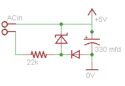
This regulator converts mains 120VAC to 5V; mains is plugged into the connection indicated, with hot connected to the upper wire and neutral the lower wire.
To explain how this circuit works and how to size components, let me simplify it. First, let’s consider the AC input signal, which is a hot wire and a neutral wire whose voltages differ by a 120VAC sine wave. An oscilloscope reading I took of mains is shown below.
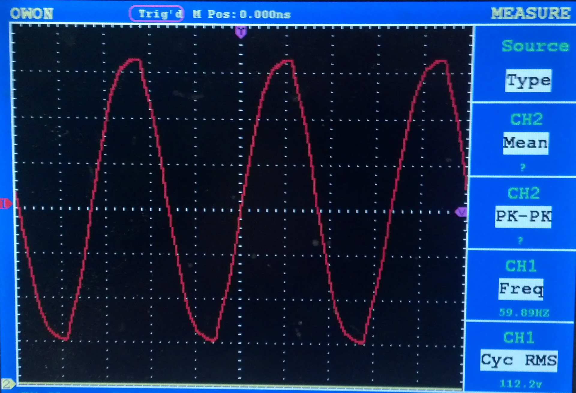
The resolution is 50V/div. Mains provides roughly a sinusoidal waveform.
However, since what we intend to be the 5V node of the power supply is connected to hot, let’s instead consider the relationship between hot and neutral with hot as our reference voltage. This is still a sine wave, we’re just using neutral as our fixed reference, as shown in the following plot, where neutral is blue and hot is red.
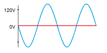
Neutral is in blue and hot is in red.
The rectifier diode (the non-zener diode in the circuit) may make this circuit hard to understand for someone who understands a regular zener regulator, so let me replace it with an ideal diode with no diode drop–it conducts like a wire when it is forward biased and does not conduct when it is reverse biased. Then, the circuit is always one of the two circuits in the following image.
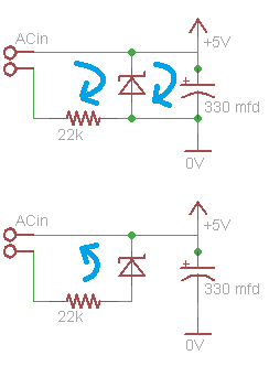
This image shows two circuit representations if the diode were replace by an ideal diode with 0V forward voltage. The 0V forward voltage is inaccurate and is close to 0.7V, but in the actual circuit, the zener diode compensates for this because it is not actually a 5V zener but close to 5.6V.
During the first half cycle of the plot of neutral above, when neutral is negative with respect to hot, the diode conducts, so current flows from hot through the zener, capacitor (until it charges), and system load. Then, the sum of these currents flow through the 22k resistor to neutral. Due to its conduction characteristics, the zener diode drops at most 5V, and so the capacitor charges up to this voltage. The zener was selected specifically to have a low required zener current (on the order of 1 mA). The 22k resistor was sized to allow enough current for the system to run and the zener diode to zener while limiting the current to be less than the amount that would destroy the zener.
During the second half cycle, neutral is positive with respect to hot, to the diode is biased in the opposite direction. Current still flows through the resistor, but in the opposite direction and back through the zener. However, current does not flow from mains through the capacitor or the rest of the system. Rather, the microcontroller draws current from the capacitor, and it slowly discharges. The capacitor was sized such that it could power the microcontroller for one half cycle without its voltage drooping significantly. The 330mfd capacitor chosen corresponds to a 10% droop. I later shrunk the capacitor, taking note that this particular controller actually runs on as low as 2V.
Notably, the resistor could actually be larger, as a 22k allows as much as 7mA, and at 22k, the resistor dissipates on the order of half a watt, more than ought to be dissipated by a quarter watt resistor. In my circuit, the resistor heats up considerably. In future versions, I’ll replace this with a larger resistor, such as 220k. The 22k size is an artifact from the size chosen in the original application note, which appears to be a typo. Equation 5 of the application note incorrectly comes to the conclusion that passing a 0.7mA current across a 110VAC drop requires a 22k resistance when actually this number is 220k. The application note also spreads the power dissipation across two quarter watt resistors.
Based on this explanation, we could imagine systems where it is not the case that logic 0V is disconnected to the neutral of mains. For example, we could rearrange the regulator such that the 0V node is connected to neutral and the 5V node passes through the 22k resistor to hot. However, then we would also have to place the triac below the load such that it is switching. As a result, we would be switch neutral rather than switching hot, which is undesirable because it breaks convention. Moreover, some two-terminal AC devices have their cases grounded to their neutral, so this is undesirable in terms of safety as well. Moreover, if one logic power rail (0V) is at the level of the triac, and the other is 5V above it, then we will be switching the triac in quadrants 1 and 4 rather than 2 and 3. Quadrant 4 of a triac consumes the most current, so we would prefer to avoid it. As a result, we construct a system where one logic rail (5v) is at the level of the triac, and the other is 5V below the triac.
Update: Zero Detector
Eric says I should write about the zero detector, too, so I’m adding a section here. He says:
cool
you didn’t talk much about the zero crossing detector which i think is almost as cool as the regulator
since you can’t just take 120 VAC and put it into a microcontroller pin
but they tapped it off the pre-capacitor regulator
Basically, the voltage at the node between the zener and rectifier alternates between slightly above +5V (due to the zener diode forward drop) and slightly below 0V (due to the rectifier forward drop). As a result, this a great node to use for zero crossing detection.
Etch Mask with Spray Paint and Laser
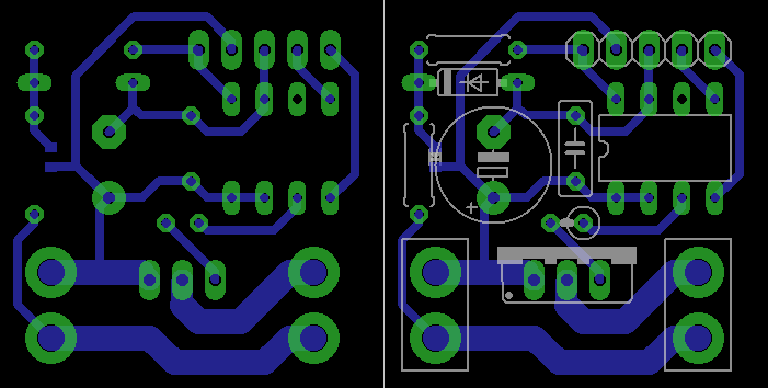
Left shows the copper traces while right includes an overlay of the components.
After designing the schematics and laying out my PCB in Eagle, I created my PCB. I used a mask technique described in a couple guide online, which I will redescribe here. First, I cut my copper clad sheet and cleaned it with acetone and steel wool. Then, I coated it in 2-3 coats of spray paint.
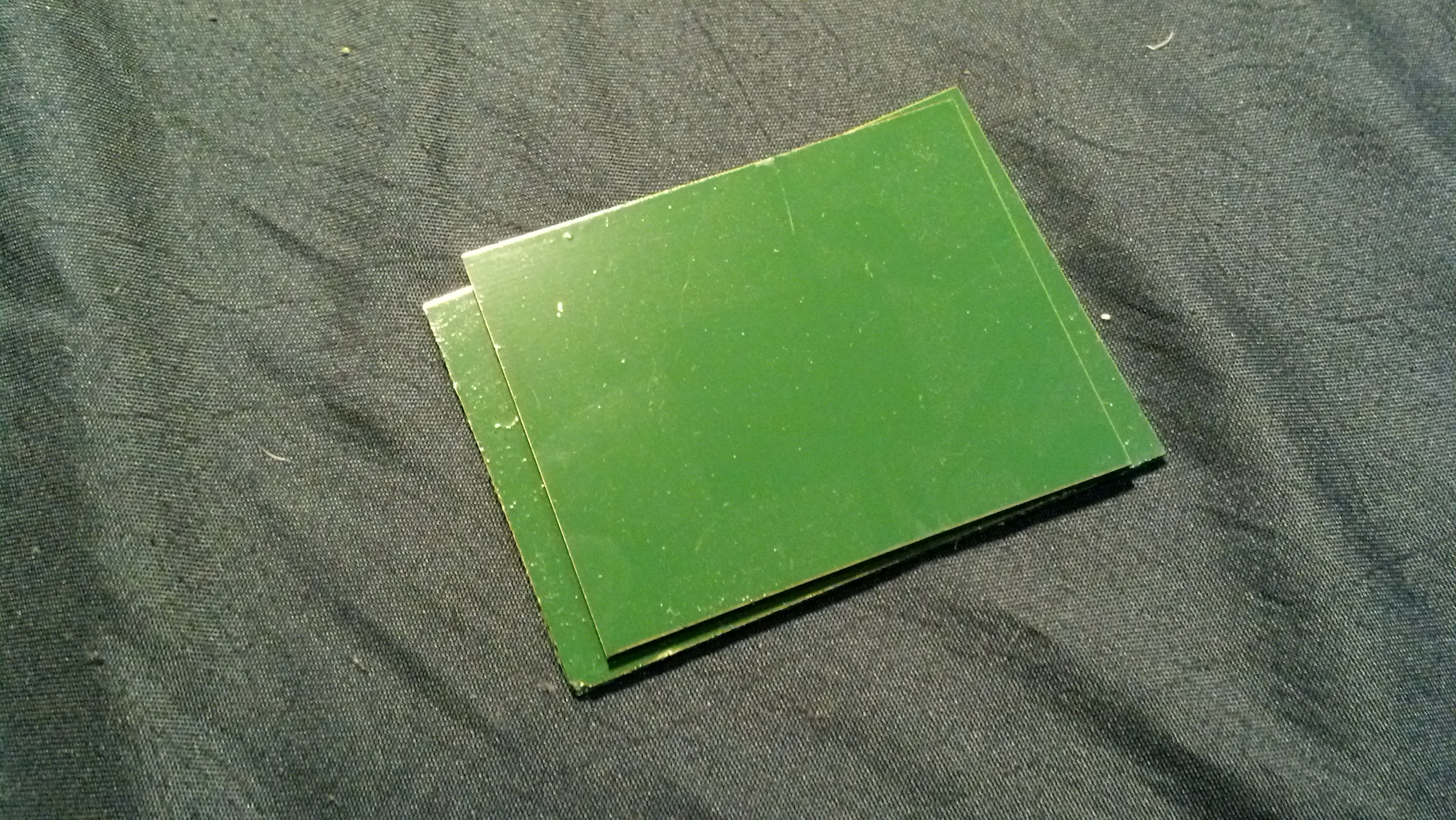
I first used green-painted copper clad sheet but later used white-painted sheet after I attempted to etch the former with some bunk etching solution.
Next, I used a laser cutter to blast off the paint in areas I wanted to etch.
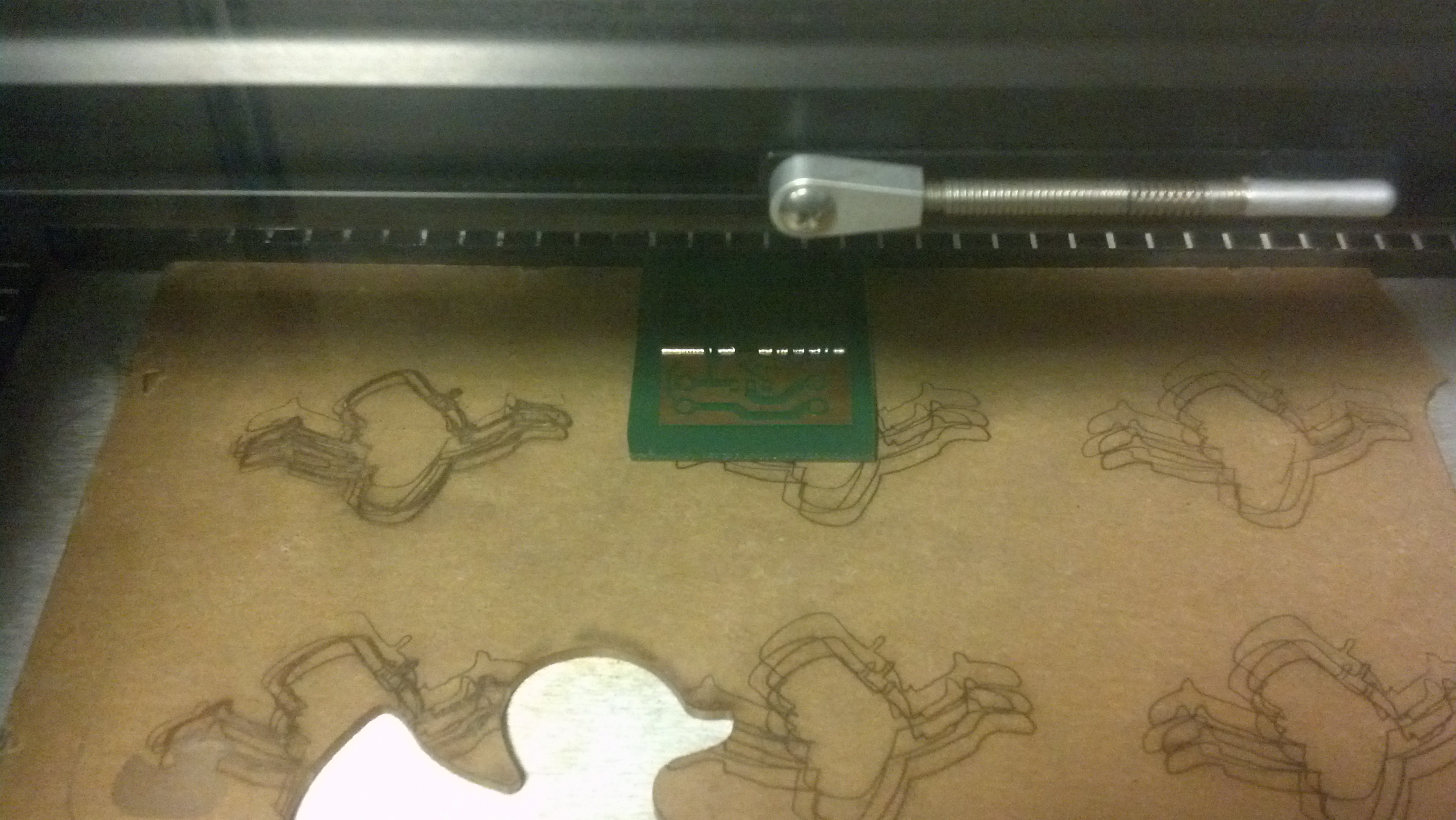
lazors
Finally, I etched the board like normal and used acetone to remove the paint.
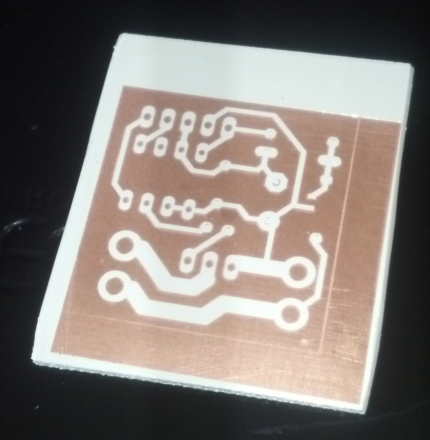
Here’s the circuit I finally etched, with white spray paint mask.
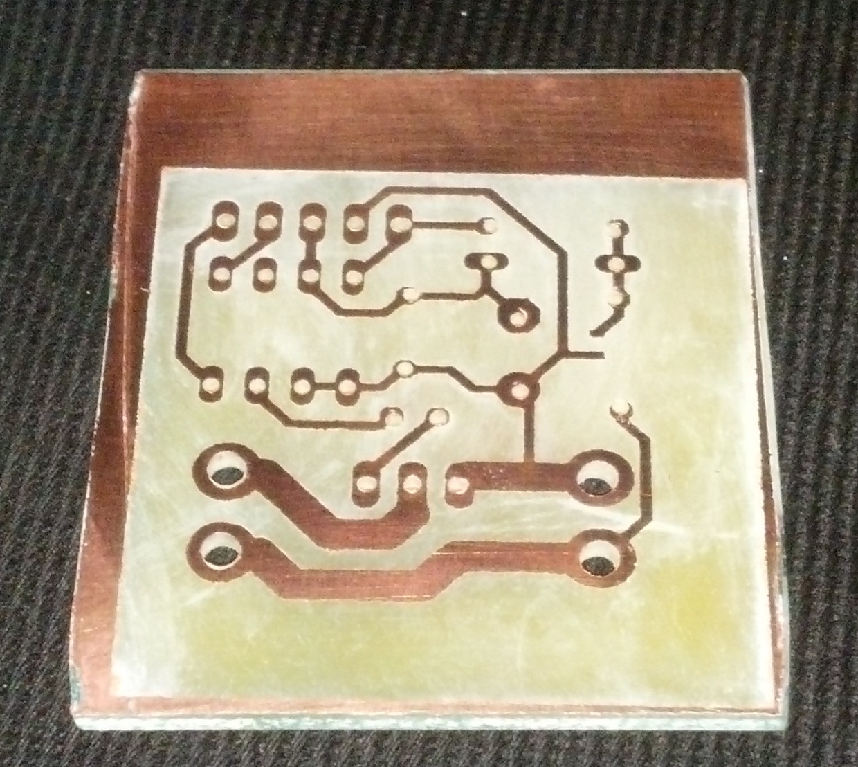
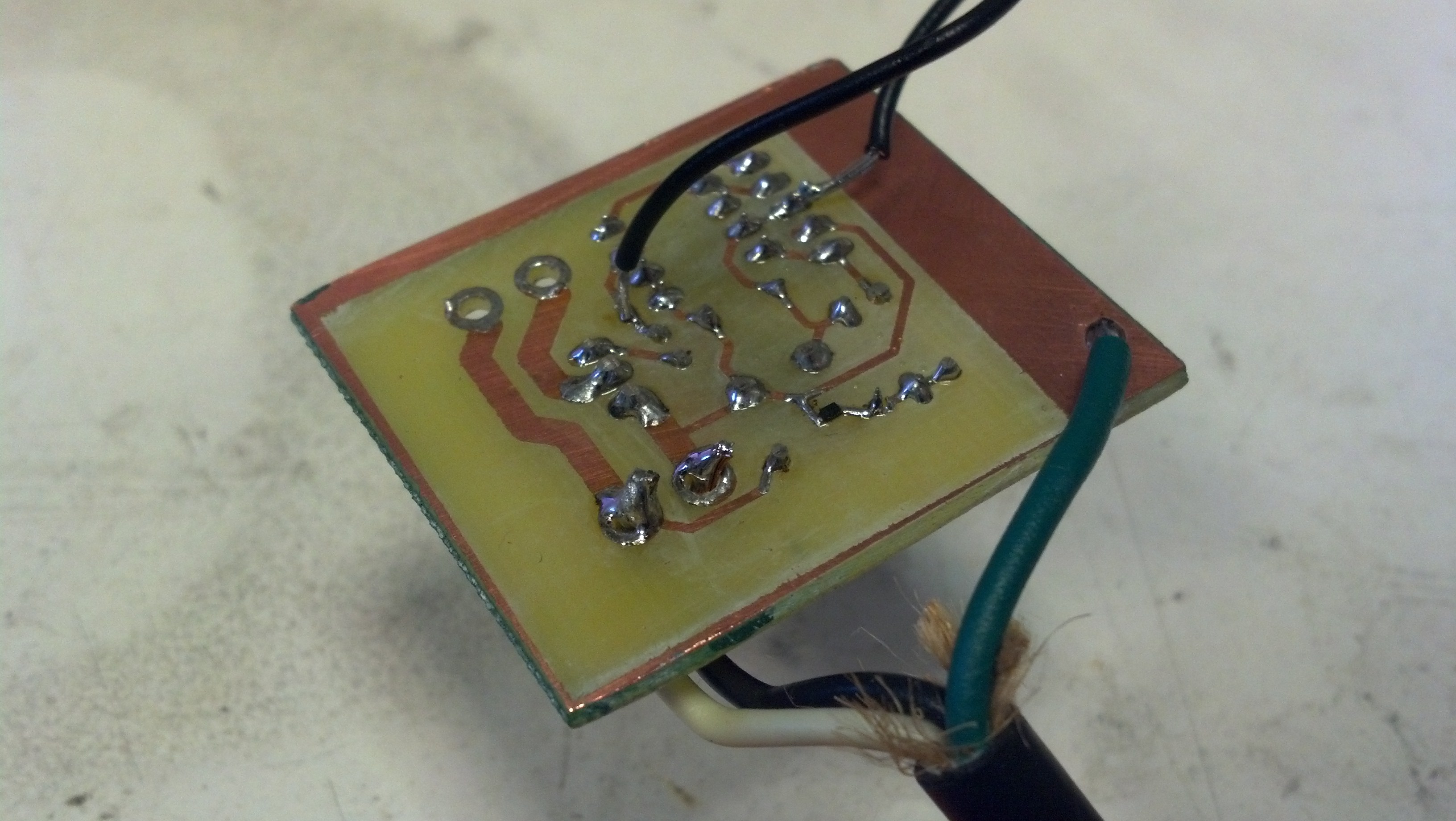
After I etched the board and acetoned off the paint, I drilled holes in the PCB.
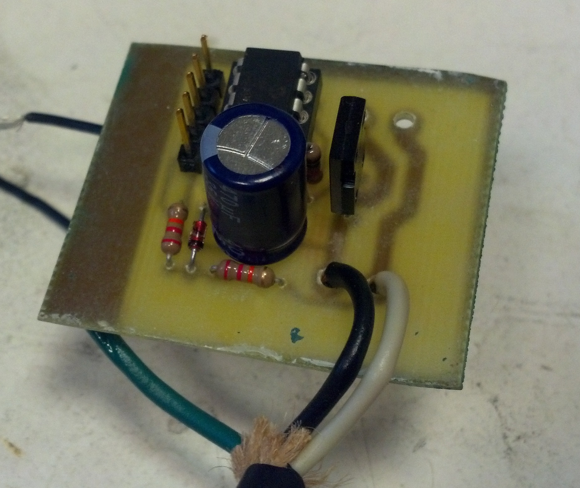
After etching, I populated the board, debugged it, powered it on, and programmed it. Don’t touch this! Mains is exposed here in bare copper. I plan to encase this for safety.
Software and Debugging
Next, I debugged and programmed the system. The microcontroller pin connected to the circuit through a 22k resistor is for zero crossing detection. I was hoping to use the sleep function of the microcontroller to put the microcontroller in a low power state until a change was detected on this pin, indicating zero crossing, but I realized the microcontroller had no memory between resets, so I could not implement this while also implementing a fade effect, which requires a counter that passes its state cycle after cycle. Instead, I just looped my program until a change was detected on the pin.
For simplicity, I designed with entirely through-hole components, except for my zener because I could not find low enough current zener that was through-hole. The two black wires were temporarily attached for debugging.
As indicated before, debugging was difficult because I could only measure differential measurements with my grounded oscilloscope. Initially, this proved to be ineffective because the oscilloscope could not provide volt-scale resolution on differential measurements while reading 120V measurements. I attempted to use a high voltage differential probe, but this also proved ineffective for measurements on the order of volts. Ultimately, I connected my circuit to mains through an isolation transformer, allowing me to probe the 0V and 5V nodes directly.
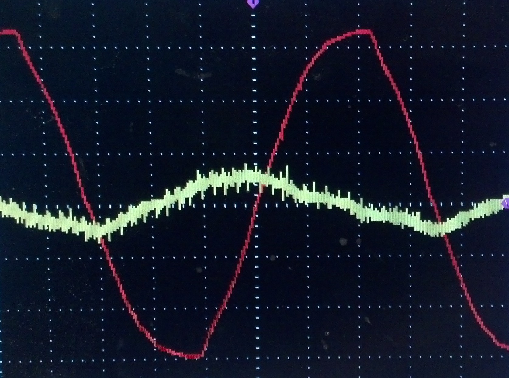
This oscilloscope reading shows two signals of different scales. Red is neutral measured relative to hot, at 50V/div. Yellow is the 5V power supply, measured at 20mV/div. Yellow has a ripple roughly 30mV peak to peak. During one half cycle, the capacitor recharges, and during the other, it discharges.
Check it out in action!
You can see in the video above that I shrunk the capacitor per my above note about sizing.